|
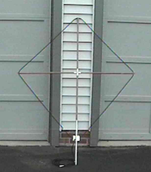
A 3805er up against the garage |
Greg Ordy
Ragchewing on 75 meters with the locals (several hundred miles) can be a lot of fun. The summer months, however, with their high static and noise levels, can be brutal on the ears. I have found that a small receive-only loop antenna can be used to make the situation much more tolerable. This page describes an easy-to-build loop that I have built several times for myself and friends. We tend to congregate on 3.805 MHz, so I call this version the 3805er.
The perimeter length of the loop is 12 feet, and it is in a diamond shape. It is approximately 4 feet wide and 5 feet tall. It is certainly possible to use the loop in the shack, although I find the performance to be better when the loop is outside.
|
A 3805er up against the garage |
In order to improve reception, it is necessary to improve the signal to noise ratio. Common 80 meter antennas such as low dipoles, inverted Vees, or verticals, suffer on receive because they have a nearly omnidirectional response pattern. While the desired signal is arriving from one direction, noise can arrive from all directions. A loop antenna such as the 3805er improves this situation because it has broadside nulls at very low wave angles. Most radio signals within several hundred miles tend to arrive at much higher wave angles (above 45 degrees), and at those angles, the loop response is nearly omnidirectional. Often times, noise is relatively local, and arrives at a low angle. The loop can be oriented to reduce the reception of this noise. Less noise, same signal, improved signal to noise ratio.
Technically, the 3805er is a single-turn shielded loop antenna. This type of loop is described in the ARRL Antenna Book, and the ON4UN book. Some sources state that the shielded nature of the loop provides additional noise immunity by shorting the (noisy) electric field to ground while responding to the magnetic field. Because of that belief, this type of antenna is also called a magnetic loop. I'm not sure if I believe that particular theory, but in any case, the loop can improve reception of short-distance radio signals.
In my experience, this type of antenna is most useful for short-distance work in the summer months. I do not consider it to be a good DX antenna, although it has been used for DX by some. When winter comes, and 80 meter noise tends to drop naturally, the advantage of the loop often disappears. Please note that the 3805er is a receive-only antenna. In order to use it, it is almost a necessity that your radio provides a separate receive antenna input jack. This antenna, like most receiving antennas, will have very low output compared to transmit antennas. In some cases, a preamp can be useful. It is entirely normal that when using this antenna you will have a nearly S0 noise level, and the station you are working will barely move the meter. What will be missing is the deafening noise crashes and static bursts that contribute to ear fatigue.
The antenna design is certainly not original. The loop is constructed from small diameter 50 ohm coax, such as RG8X. Any coax diameter or characteristic impedance can be used, so long as an appropriate capacitor resonates the antenna at the desired frequency.
In order to preserve the broadside nulls, the literature suggests that the length of the loop wire should be less than 0.1 wavelength. That limits our perimeter length to no more than 25 feet. I chose the 12 foot length since it naturally falls out from using standard 4 foot dowels for spreader arms. I also wanted a loop that could be used inside as well as outside, and the 4 foot dowel-based form is light and not difficult to move around.
I use a small trimmer capacitor to resonate the loop at the desired frequency, 3.805 MHz. A loop built following my dimensions and geometry has an inductance of approximately 5.3 uH at 3.805 MHz. This is around 125 ohms of inductive reactance. A 325 pF capacitor will be needed to achieve resonance. I happened to have a bag of 270 pF hamfest trimmers, so I parallel an 80 pF silver mica capacitor across the trimmer to get up to the needed value. I also usually include a small step-up transformer to match the low loop impedance to the 50 ohm feed line. This is an optional part of the design. I do find that the addition of the transformer increases loop output. The transformer is wound on a 1/2 inch ferrite core. Any mix suitable for the frequency will do (#75 (best), #43, etc.).
|
3805er Schematic |
In order to build your own 3805er, collect the following parts:
Parts List |
|
Part Description |
Quantity |
| 12 feet of 50 ohm mini coax (RG8X) | 2 |
| PL-259 coax connector with mini coax insert | 1 |
| 4 foot dowel rod, 5/8 inches in diameter | 2 |
| 3/4 inch aluminum tubing, 3 inches long | 2 |
| 3/4 inch aluminum tubing, 18 inches long | 1 |
| 2 3/4 inch X 2 1/8 inch X 1 3/4 inch aluminum project box | 1 |
| 1/4 inch grommet | 3 |
| 1/4 inch X 20 stainless steel bolt, 2 inches long, and locking nut | 1 |
| 1/4 inch screw eye | 3 |
| #8 X 1/2 inch long stainless steel machine screw | 3 |
| terminal strip, 5 lug | 1 |
| variable trimmer capacitor, approx. 350 pF (see text) | 1 |
| cable ties, small | 3 |
| cable ties, large | 3 |
| 1/2 inch ferrite core toroid, #75 or #43 material | 1 |
| solid hookup wire, #22 | 2 feet |
| electrical tape | 8 inches |
|
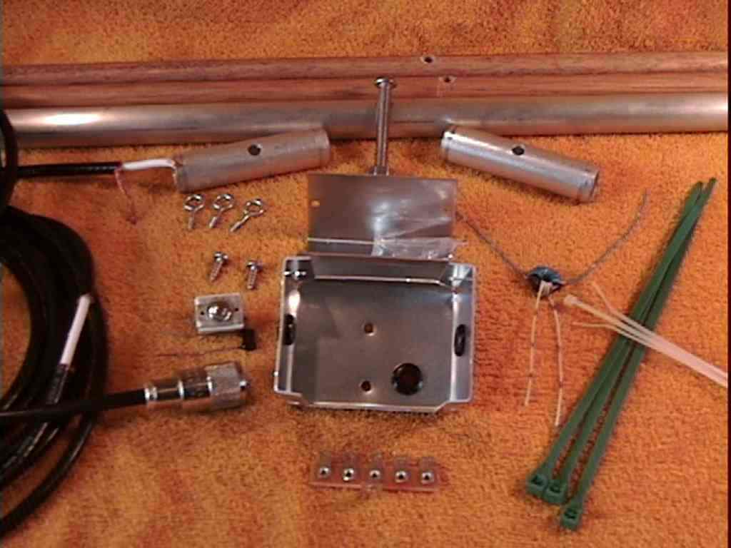
3805er Parts |
In addition to these parts, and common hand tools, you will need a drill and several different drill bits. One bit makes the hole for the grommets. For a 1/4 inch hole grommet, a typical drill bit size is 3/8 inch. You will need a 1/4 inch drill bit for the 3 inch aluminum tubes and the 1/4 inch X 20 stainless steel bolt that joins the tubes and dowels. Finally, you will need a drill for the #8 screws that attach the project box to the 18 inch aluminum tube. The bit needs to be slightly smaller than the screw so that you can use the screw in a self-tapping manner. The diameter is approximately 1/8 inch, but size it according to your screws.
If you wish to accurately resonate the antenna, and optimize the output of the antenna, you will need an antenna analyzer that measures SWR as a function of frequency.
Here's how I assemble a 3805er.
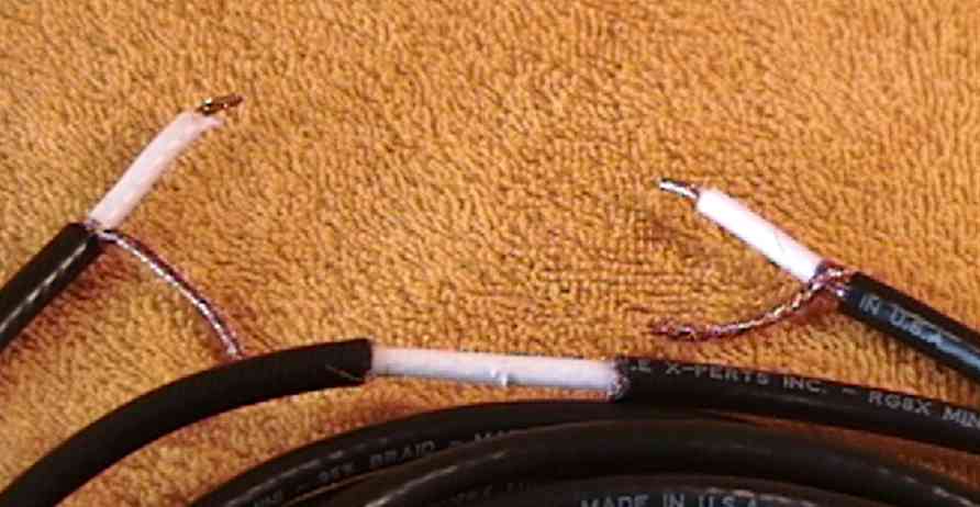
Select one 12 foot length of coax to be the antenna. To both ends, remove 1 inch of the outer jacket, and collect the braid into a single stranded wire. Remove 1/4 inch of the inner conductor insulation. Find the middle of the coax (6 feet from either end). Remove a 1 inch section of the outer jacket, and then remove the braid from around this 1 inch region. The braid must be electrically broken at this point. Seal the exposed braid ends, especially if you are going to mount this antenna outside. I paint the braid ends with liquid electrical tape, cover the entire exposed area with electrical tape, then finish off the region with a piece of heat shrink tubing. No doubt this is overkill.
|
Dressed coax ends and braid removed from center of antenna coax |
The other piece of coax is the feed line. I have found that a 12 foot length with a PL-256 plug lets me move the antenna to my various sites and simply plug it in and go. If you would prefer a different length or connector, certainly adjust my comments to your situation. Whatever the length and connector, prepare the antenna end of the cable as in the previous step. Remove 1 inch of the outer jacket, collect the braid into a single stranded wire. Remove 1/4 inch of the inner conductor insulation.
I like to apply some sort of stain/protector to the bare wooden dowels. In some climates, a bare dowel will barely last a year. With staining, mine last for many years.
Place a 3 inch aluminum tube over each dowel, and center it over the center of the dowel. With normal aluminum tubing wall thickness, the 5/8 inch dowel will fit snugly within the 3/4 inch tube. You could use other combinations of dowels and tubes so long as the dowel fits within the tube. I find that this combination is a good balance between strength and size.
Drill a 1/4 inch hole in the middle of each 3" aluminum tube. Since the dowel is in the tube, you will also drill a hole in the dowel. Try to keep the hole in the center of the tube, perpendicular to the tube length.
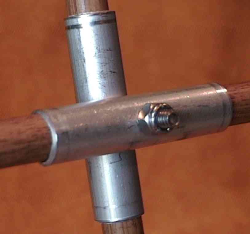
Put the 2 inch stainless steel bolt through the two tube/dowel assemblies. You should now have a cross or X of dowels. Place the locking nut over the bolt end in order to keep the arms together.
|
Center of the loop, showing 3 inch tubes around dowels with bolt as center pin |
Install the screw eyes into 3 of the 4 dowel ends. The end without a screw eye is the bottom of the antenna.
With the cross in front of you, on the floor or a table, lay out the antenna coax around the perimeter of the cross. The ends of the coax come together at the bottom of the antenna. That is the dowel end without a screw eye. The middle of the antenna, where the break in the braid is located, is at the top of the antenna. Take the three larger cable ties and put them around the coax and through the screw eyes. You do not need to pull them tight at this point. Keep a little slack in them at this point so that the antenna coax can shift around as the junction box is installed.
Drill three, 3/8 inch holes in the aluminum junction box for the antenna ends and the feed line. All of the holes are drilled in the piece that has the ends. Drill a hole in the center of each end for the antenna. Drill the feed line hole in the lower right corner of the same piece when looking into the piece (see the parts photo). Put a grommet in each hole.
Drill two more holes in the same piece. These two holes, approximately 1/8 inch, are for the two sheet metal screws that hold the box to the 18 inch aluminum tube. The upper hole also holds the terminal strip. See the picture for more information.
Put the coax ends through the appropriate holes. The goal now is to attach the small cable ties to the coax so that the ends cannot be pulled out of the box. My experience has been that a small cable tie, wrapped twice around the coax, holds much better than a larger and more stiff cable tie wrapped once. I locate the tie about 3/8 of an inch from the end of the outer jacket, on the outer jacket. Wrap the tie twice around the coax, and pull it tight. As you pull the excess coax out of the box, the ties will hit the grommets and prevent the coax from being pulled out of the box. At this point you should have three dressed coax ends in the box, with sufficient length to reach around in the box.
Measure 7 inches from one end of the 18 inch aluminum tube. Drill a hole with a diameter that will grip the #8 stainless steel sheet metal screws.
Put that end (nearest the screw hole) onto the bottom dowel. If the coax is already tied to the dowel ends, it will be necessary to put the tube over the dowel before attaching the box. If you attach the box before putting the tube on the dowel, you will have to remove the antenna from the dowel ends in order to get enough slack to get the tube over the bottom dowel.
Put a sheet metal screw through the terminal strip, through the box, and screw it into the hole in the 18 inch tube. The tube should be positioned so that the antenna wire is not offering any resistance, but not so far up the bottom tube that the screw enters the dowel.
With a single screw holding the box to the tube, align the box so that it is sitting squarely on the tube. Drill a hole into the aluminum tube through the remaining box hole. Insert a second screw into that hole, and screw into the tube. The aluminum box is now securely mounted on the tube.
With the box mounted on the tube, and the antenna running out of the box and around the ends of the dowels, the tube can be pulled away from the center of the antenna, taking up any slack in the antenna coax. If the antenna is unbalanced around the perimeter of the antenna, adjust it at this point. Snug up the cable ties on the dowel ends. Come down about an inch from the end of the tube over the dowel, and drill a hole to hold the last #8 screw. This screw must penetrate into the dowel.
Mechanical assembly is now complete. All remaining electrical work takes place inside the box. The box is a rather cramped place. The three coax cables are somewhat rigid. I find that a 30 watt pencil-style soldering iron works well for soldering connections in the box
Connect the three coax braids together, and connect them to the ground lug of the terminal strip. This means that the box and the 18 inch aluminum tube are grounded. I have built loop boxes where the feed line is connected exclusively to the secondary of the impedance matching transformer. Ground is therefore not common between the feed line and the loop shield. I could not tell a difference in loop performance. Either way seems equivalent.
Connect the two antenna center conductors to two nongrounded terminal strip lugs. Connect the trimmer capacitor to the same terminals. I find that the terminal strip is more than strong enough to support the trimmer.
Select one side of the trimmer to be the loop output. It can be either side of the trimmer.
If you are not using a matching transformer, you are done. Electrically, the trimmer is connected across the loop wires and the output signal is taken from either side. If you wish to add the transformer, follow the remaining step.
Through experimentation, I have found that with #75 ferrite material on a 1/2 inch core, the transformer primary is 5 turns, and the secondary is 15 turns. The primary, the low impedance side, is connected to the loop output side of the trimmer. The other end of the primary goes to ground. The high impedance side (15 turns) connects between the feed line center conductor and ground. I use solid hookup wire to make the windings.
Connect the antenna to an antenna analyzer. Set the analyzer to the desired frequency on the 80 meter band. If your analyzer provides antenna reactance (X) data, adjust the trimmer for resonance, that is, reactance equals zero. If not, adjust the trimmer for the lowest SWR. If you are using the matching transformer, you should be able to achieve a 1:1 SWR. I add or subtract turns on the secondary until I get a 1:1 SWR (once I am at resonance). If you are not using the matching transformer, then the point of lowest SWR is probably not the point of resonance, but they should be close.
Assuming the addition of a transformer to match the loop to the coax and provide a 1:1 SWR at resonance, the 2:1 SWR bandwidth was measured to be 36 KHz. Once you get approximately 50 KHz away from resonance, the loop signal (and noise) output will drop by several dB. This is not really a problem, as most all receivers have more than enough gain to compensate. Still, if you want maximum output from the loop, you should adjust the resonance point to your desired frequency.
It is almost a necessity to use a radio that has the ability to accept a separate receive antenna. Fortunately, this feature is becoming standard on most all recent vintage radios.
There are a number of ways to mount the antenna. For inside use, you could simply lean it up against a wall. The antenna should be kept vertical, and potentially rotated to null out local interference. I had a used wooden spool for holding coax that provided a good mount though the center hole. I simply laid the spool on its side, and placed the 3/4 inch aluminum tube base in the spool hole. You could also take a piece of wood, such as a foot long section of a 2X6, and drill a 3/4 inch hole in it to act as a base.
Outside, the simplest mount would be to push the 3/4 inch aluminum tube into the ground. the only down side of this approach is that the tube will get filled with dirt. A variation on the this theme is to drive a short length of 5/8 inch tubing into the ground, then slip the antenna tube over the 5/8 inch tube, since the two sizes telescope. Now the antenna tube will stay clean, and the antenna can be easily rotated. I have also used an elastic cord to strap the antenna to a deck railing. The antenna could also be hung from a low tree branch with a short length of strong string.
Some sources suggest putting a loop on a rotator so that the nulls can be easily moved. I have never had this setup, so I cannot comment on its value. It is interesting to use the loop in the shack, however, where it can be turned by hand. I find this especially interesting right before sunset. So long as there is daylight, it's a good bet that most signals are arriving via ground wave, at a very low angle. As you rotate the loop, the broadside nulls will be quite obvious. There should be very little advantage in raising a loop high off of the ground. Operation at ground level is just fine.
I prefer the loop outside. I have mounted mine on a wooden deck handrail, a few feet off of the ground. This gives me the best results. Inside my second story bedroom shack, there is too much local noise (computers, TVs, etc), and I believe that I lose a few dB of signal (and noise). This is compared to being out in a flat field, almost 100 feet from the nearest building.
Back to my Experimentation Page