 |
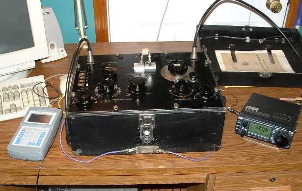 |
| General Radio 821-A Bridge | Test Setup |
Greg Ordy
Q, the quality factor. A somewhat mysterious and dimensionless metric which turns up over and over again, in many different contexts (even on Star Trek). On this page, Q refers to the quality of the reactive components (capacitors and inductors) used in my Hex Array phasing networks.
In this application, these components have the additional demand that they be able to accept the power coming from a transmitter. For that reason, I'm calling them RF transmitting components, but many other names could apply.
Q is defined to be the reactance divided by the resistance. What reactance and resistance are we talking about? They are the series form reactance and resistance of the component (capacitor or inductor). In this case, the higher the value of Q, the better. Any value other than infinity indicates that the part has some nonzero resistance, and that resistance is a source of loss. The loss is a problem for at least two reasons. First, it heats and stresses the component, and in the extreme, heat will lead to failure. Second, the resistance throws off the impedance transformations of capacitor/inductor networks. This is because the typical formulas used to compute L, PI, and Tee networks ignore resistance, and assume components with only reactance. Unless the Q is very low, however, the impact is usually small.
| Q = X / R | Eq 1 |
| Z = R + j X | Eq 2 |
Resistance and reactance can be measured by the traditional impedance bridge. Component Q is nothing more than the reactance divided by the resistance. In practice, we want the resistance to be very low, near zero Ohms. This means that the impedance bridge must have enough accuracy and sensitivity to measure and resolve fractional Ohms near zero. This suggest a high quality impedance bridge. Stand-alone Q meters also exist, and some are quite accurate and also expensive.
Conventional wisdom states that the Q of (most) capacitors is high enough that for all practical purposes, effects due to Q can be ignored. An estimated capacitor Q value which appears in many sources is 1200. Problems due to Q are usually associated with inductors. Many sources state that if you build a very high Q inductor you can get up to a value of 800. In practice, values are often under 300, perhaps under 100. The only way to be absolutely sure that component Q will not be a problem is to measure the Q of all of parts, and carry out all impedance transformation and component power rating calculations with Q being taken into account. This is a lot of work, even for passive networks with less than a dozen parts (as mine are).
My approach to the impact Q in the design of my phasing networks was to largely ignore it. I set out to maximize Q for the obvious reason that it reduces problems. When it came to component ratings, I wanted to have a large safety margin in the power, voltage, and current ratings. So large that any additional loss (and therefore heating) due to the invisible Q would not cause my networks to fail.
The measurements reported on this page were made after I completed my phasing networks, and were made because I had access to an impedance bridge which could report Q, and I was curious to see what sort of Q values I was working with in my implementation - how did conventional wisdom match match my measurements.
In retrospect, I see two problems with this approach. While I was able to achieve the desired current magnitude and phase relationships on each band, the networks required tweaking to achieve the best performance. Theoretically, I had done all of the measurements and calculations necessary to compute the networks exactly, without need for tweaking. Now let's get serious here. There were many places where errors could creep into the process. The accuracy of my impedance measurement equipment. The accuracy of my component measurement equipment. The computation of loss in the transmission lines. These are three areas where error could easily enter the process. Still, in the end, I had a sense that there were additional factors that I was not taking into account, and phasing network component Q is a possible (but low probability) explanation. The second problem is that after I made these Q measurements, I saw that some doorknob capacitors in my junk box had a very low Q. I suspect this is a defect present in some percentage of the parts. Perhaps this explains why they were so inexpensive at the local hamfest? I would have liked to screen my capacitors for Q problems before using them, and reject any low Q parts. I would add that step in the future.
References and links for Q, capacitors, and inductors.
The ARRL Handbook, by the ARRL. Lots of information on RF components, including Q.
RF Circuit Design, by Chris Bowick (WD4C). Published by Newnes. A complete introduction to components and Q. An excellent reference on a number of RF topics.
Radio Engineering, by Frederick Terman. Published by McGraw-Hill. Many consider this book (there were 4 editions) to be the bible of electrical information. I have the third edition from 1947. There is a very good explanation of the various capacitor loss metrics, which I quote below.
Ferromagnetic Core Design & Application Handbook, by Doug DeMaw, W1FB. Published by MFJ Publishing Company. An extensive look at cores in many different applications.
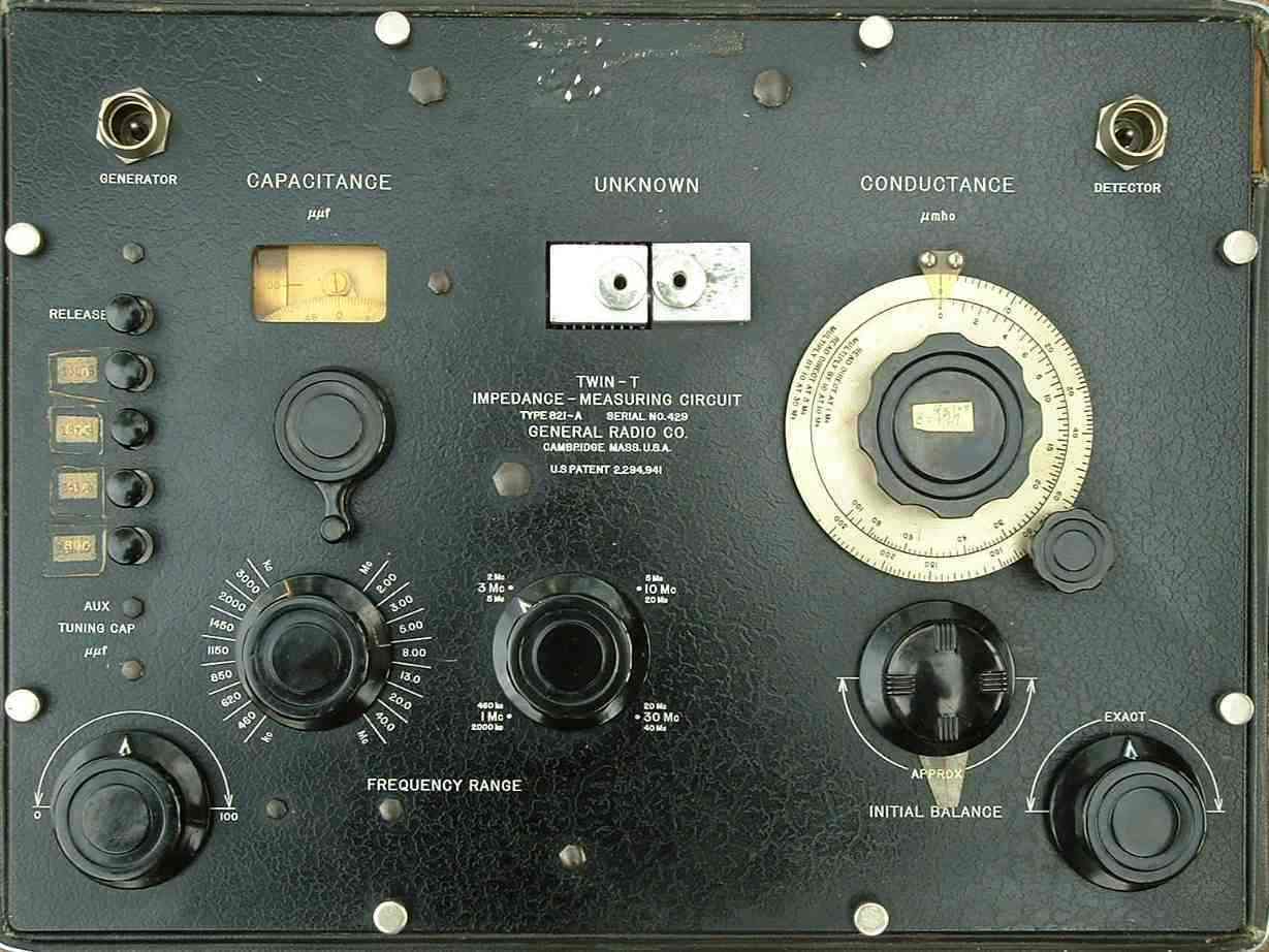
The test setup is based around the General Radio 821-A Twin-T Impedance Bridge. This nearly 50 year old device measures susceptance (capacitance) and conductance, which can be converted into impedance (resistance and reactance) and Q. This conversion is aided through the use of an applet created by W9CF. This applet applies several compensations which are suggested in the 821 documentation. These tweak readings to be closer to the truth. It is also possible to custom set the compensation parameters, but I did not do that for these measurements.
Since the 821 is a traditional bridge, it requires a signal generator and a detector. I used the AEA CIA-HF antenna analyzer as a signal generator, and an ICOM 706MKIIG radio as the detector If you are using a receiver as a detector, you usually want to set the AGC to the fastest possible setting. Please click on a picture for a larger view.
|
|
|
| General Radio 821-A Bridge | Test Setup |
In order to use the bridge you must be able to find the nulls. When the bridge is not balanced, the input RF signal passes through the bridge, and is very strong at the detector, which is a receiver in this case. The capacitance and conductance knobs are both adjusted until the signal drops at a null. The nulls are quite deep (nearly 100 dB), and quite narrow. In the end, you are literally nudging the knobs ever so slightly to reduce the signal output to nearly zero.
When you want to take a reading, the knobs are set to an initial state, and the null is set with the trimmer controls. This initial balance can include any test leads, so that they are not part of the final reading.
The device under test is connected to the two large terminals on the top middle of the cabinet. Use the shortest leads, ideally no leads at all. When the device is connected, the second null is found. Data readings are taken from the large dials, and input to the applet. It applies the conversion and correction factors, and computes the impedance and Q.
I decided to use ceramic doorknob capacitors in the full-power networks. These parts are available from a number of sources, including hamfests. I've paid between $1 (used) and $10 (new) for a single capacitor. The 5 kv model 850 is the lowest voltage entry point. These units can pass several amps of current, and in my case, I used several in parallel to achieve a certain capacitance. This parallel arrangement increases the overall current rating of the combination. Doorknob capacitors are available in a range of power handling limits (5, 7.5, 10, 20 kv...). As the ratings rise, the parts get a little larger. Please see the I0JX page for additional information and details.
Another factor which can be important is the temperature characteristic of the capacitor. This specification indicates how the capacitance value changes in response to changes in temperature. The most desirable parts are the NPO type, which have a very low (practically zero) change in capacitance.
From what I have observed, common doorknob capacitors range between 20 and 1000 pf. The lower pf values are more available, less expensive, and more likely to be type NPO. It's relatively easy to find doorknobs under 100 pf. The 500 pf and 1000 pf parts are much harder to find, and more expensive, and usually not NPO.
Here are pictures of a capacitor being tested, and the set of capacitors and inductors that were tested. Please click on a picture for a larger view.
 |
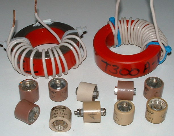 |
| Capacitor Under Test | RF Transmitting Capacitors and Inductors |
I selected 12 capacitors from my junk box covering 28 to 1000 pf. I measured their capacitance, impedance, and Q at three frequencies, 1.5, 3.8, and 9 MHz. These frequency values were chosen to be representative of the lower amateur bands, and they were also frequencies where capacitance measurements were easier to make on the 821-A bridge.
|
Capacitor Q Measurements, October 13, 2003, General Radio 821-A Bridge |
|||||||||
| 1.5 MHz | 3.8 MHz | 9 MHz | |||||||
| Cap. | pf | Z | Q | pf | Z | Q | pf | Z | Q |
| #1: 28 pf NPO | 26.03 | 0.49 - j 4076.15 | 8390.0 | 27.57 | 0.60 - j 1519.33 | 2545.8 | 28.79 | 1.10 - j 614.24 | 559.9 |
| #2A: 63 pf | 63.27 | 0.20 - j 1676.97 | 8536.3 | 63.97 | 1.62 - j 654.72 | 403.6 | 65.20 | 0.48 - j 271.22 | 569.7 |
| #2B: 63 pf | 64.27 | 0.19 - j1650.85 | 8540.3 | 64.14 | 0.25 - j 652.68 | 2599.7 | 63.54 | 0.49 - j 278.31 | 569.2 |
| #2C: 63 pf | 64.27 | 0.19 - j 1645.72 | 8541.1 | 65.48 | 0.25 - j 638.67 | 2601.8 | 64.79 | 0.48 - j 272.96 | 569.5 |
| #2D: 63 pf | 64.27 | 0.19 - j 1645.72 | 8541.1 | 64.17 | 0.25 - j 652.58 | 2599.7 | 65.62 | 0.47 - j 269.50 | 569.8 |
| #2E: 63 pf | 64.27 | 0.19 - j 1645.72 | 8541.1 | 62.36 | 0.26 - j 671.62 | 2597.0 | 61.88 | 0.50 - j 285.79 | 568.8 |
| #3: 200 pf, 20% | 203.60 | 0.06 - j 521.15 | 9136.8 | 203.57 | 0.28 - j 205.74 | 746.7 | 208.33 | 0.14 - j 64.88 | 611.8 |
| #4: 400 pf, 20% | 399.09 | 0.03 - j 265.86 | 10129.0 | 401.33 | 0.19 - j 104.36 | 563.8 | 416.78 | 0.06 - j 42.3 | 685.7 |
| #5: 500 mmf (pf) | 453.51 | 0.02 - j 233.45 | 10451.0 | 457.53 | 0.32 - j 91.54 | 285.2 | 474.97 | 0.10 - j 37.23 | 381.4 |
| #6: 500 pf, Hi-K | 497.91 | 4.51 - j 213.00 | 47.2 | 498.30 | 2.33 - j 83.99 | 36.1 | 502.85 | 1.01 - j 35.14 | 34.9 |
| #7: 1000 pf, X5V | 1060.28 | 0.06 - j 100.07 | 1552.4 | 1066.15 | 0.18 - j 39.28 | 223.9 | 1205.33 | 0.08 - j 14.67 | 175.7 |
| #8: 1000 pf, X5U | 844.59 | 0.53 - j 125.62 | 238.4 | 852.99 | 0.50 - j 49.10 | 99.2 | 945.92 | 0.29 - j 18.69 | 64.7 |
The Cap. column includes an identifying code (#1, for example), and the main markings on the capacitor body. In order to make readings which did not require an extra step that could lead to additional error, the 1000 pf parts were measured at 3.2 MHz, not 3.8 MHz. This is just the nature of the 821 bridge, and how the frequency range is split over various control settings.
Since I had a large number of 63 pf units, I decided to measure 5 parts to get a sense of the variation between them. This is the #2 series, from #2A to #2E.
Capacitive reactance varies inversely with frequency. As the frequency goes up, the capacitive reactance drops (Xc = 1 /( 2 * PI * F * C)). What appears to be the case is that these capacitors have a small amount of resistance around 0.5 Ohms which is always present and doesn't change much. The Q, therefore, is greater at lower frequencies where the reactance is higher. This also means that parts with a higher capacitance will have a lower Q, since more capacitance implies less reactance. The highest Q is found in a lower capacitance part at a lower frequency.
When we get up to 9 MHz, the Q values have all dropped under 700. What concerned me most about these measurements was the Q of capacitors #6 and #8. Both are relatively low. It's hard not to call part #6 a bad part. Even part #7, which has a high Q of 1552.4 at 1.5 MHz drops to a Q of 175.7 at 9 MHz. My conclusion is that high capacitance doorknob capacitors at higher HF frequencies will have Q values which can become quite low. Q values can probably be extrapolated from this data.
A number of different metrics have been used to describe the quality of a capacitor. The clearest and most concise description that I am aware of is on page 24 of the third edition of Terman. Since I can't say it any better, I'll repeat it here:
The merit of a condenser [capacitor] or of a dielectric can also be expressed in terms of the angle by which the current flowing into the condenser fails to be 90 degrees out of phase with the voltage. This angle is termed the phase angle. The tangent of the phase angle is termed the dissipation factor. The reciprocal of the dissipation factor is termed the condenser Q and is the ratio of condenser reactance to the equivalent series resistance, With ordinary dielectrics, the phase angle is so small that the power factor, dissipation factor, and the reciprocal of the condenser Q are for all practical purposes equal to each other and to the phase angle expressed in radians. Thus, a power factor of 0.01 represents a phase angle of 0.573 degrees and a condenser Q of 100.
I additionally measured the Q of two different capacitors, or capacitor combinations. The first measurement was of a 433 pf silver mica capacitor at 3.8 MHz. Silver mica capacitors have been considered to be excellent in RF applications. The measured Q was 1335.3. This is an excellent Q for this frequency and capacitance. The 400 pf doorknob at this frequency had a Q of 563.8. I suspect that when conventional wisdom quotes capacitor Q values of 1200, they are thinking of silver mica parts.
The next test combined three doorknob capacitors in parallel. I combined capacitors #2C, #3, and #4. Combining capacitors is something I did in my networks in order to create very specific values intended to replace trimmer capacitors which were adjusted in the field. When capacitors are combined in parallel, the capacitance values add. The test was at 3.8 MHz. If you add up the values in the previous table (at 3.8 MHz) the sum is 669.07 pf. When I measured the parallel combination, the result was 687.83 pf. If you convert the pf to reactance, and take the difference, it's approximately 1.6 Ohms, which is due to the inductive reactance of the wires connecting the capacitors together. The Q of the parallel combination was 212.7. The individual Q values were 2602, 747, and 564. Wiring capacitors in parallel will lower the total reactance, and that had the effect of lowering the Q. The resistance hovered near 0.3 Ohms, and in the face of the lowered reactance, the Q dropped quite a bit. Perhaps this lowering of Q creates an issue which limits the number of capacitors which can be placed in parallel?
Early on in the project I decided that all of my inductors would be wound on toroidal powdered iron cores. The main reason was to take advantage of the self-shielding property of toriodal cores. Traditional inductors can easily couple to each other, especially when oriented along the same axis. This is why many projects have the inductors located at right angles to each other, in order to reduce coupling. I wanted to minimize the possibility of interaction, and pack the networks into the smallest possible container.
The use of a powered iron core will also reduce the length of the wire needed to create a given inductance for a fixed diameter. The powdered iron core has an increased permeability over air, and this multiplies the inductance by the value of the permeability. Since less wire is used, there is less resistance due to the wire.
By the way, the other popular core material is ferrite. As a first cut approximation, powdered iron should be used for inductors, and any application that handles power. Ferrite is good for transformers in lower power circuits.
When selecting a powdered iron core, two important parameters are the core material and the core size. Core material is mainly a function of frequency, and core size is mainly a function of power level.
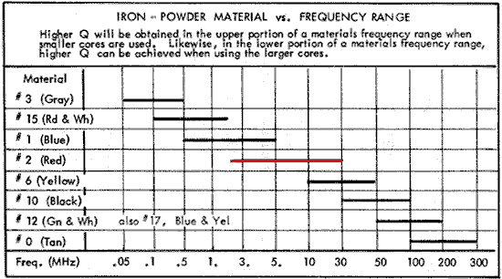
If you visit the Amidon or Bytemark web pages, or check many books and articles, you will see the following chart of core material versus suggested frequency range.
 |
| Core Material Select Chart |
I needed these cores to operate on 80 and 40 meters. The frequency span is 3.5 through 7.3 MHz. There really was only one choice which would be suggested for both bands - the #2 or red material. Red really is the color of the core. I should say that each core only operates on a single band, but I wanted to purchase one core which could be used on either band. When I ordered the cores I did not know the exact number of cores needed for each band. I did make a reasonable estimate, and since a core could work on either band, I had the flexibility to use them in either network.
The ON4UN book suggested that a 4 inch diameter (double thickness) core would easily handle over 1500 watts of RF power in this frequency range. In general, a larger core diameter can handle more power than a smaller core. Another way to increase the power rating of a core is to make it thicker. It is possible to order cores which are twice as thick as the standard thickness. It is equivalent to simply stack more than one core next to another to achieve the same effect. The way that the parts were priced, however, made it cheaper to purchase thicker cores as opposed to twice as many thinner cores and then stacking them.
I decided to standardize on type T300-A2 cores. These are 3 inch diameter double thickness cores made from #2 (red) material. The Bytemark web site shows a power rating of 1127 watts at 1 MHz for a standard thickness 3 inch core. The double thickness cores will handle more power. The power rating does go down as the frequency rises. While I do have 1500 watts entering the network, the inductors are located on the legs, after the power has been divided. In other words, most all of my components are nowhere near the full 1500 watts.
The first concern is that the core not overheat in operation and fail. The T300-A2 cores should not fail due to heat. The next concern is usually that there not be a voltage breakdown between turns on the coil. There are two types of breakdown. Breakdown between turns, and breakdown to the core itself. Prevention against this problem consists of using wire with improved voltage insulation, and covering the core itself with special glass tape which increases the breakdown voltage to the core. I did not take either measure, and my wire is common #12 or #14 solid copper house wire. The wire gauge will easily handle the current, and the insulation voltage rating is 600 volts. My turns usually have some space between them, so the air gap adds to the breakdown voltage. Even though I tried to wind the coils tightly to the core, the stiffness of the wire created some spacing between the turns and the core, and this also increases the voltage breakdown value.
One of the strong points of winding your own inductors is that you can create any desired value of inductance. It's also possible to stretch and compress the windings on a toroidal inductor and tweak the inductance, either up or down. My design approach was to build a test network with the full-power inductors and low-power trimmer capacitors, preset to the design values. I optimized the network by tweaking the trimmers, and squeezing or stretching the inductors when needed. I then removed the trimmers, and replaced them with parallel combinations of doorknob capacitors at the same capacitance value. I had enough parts in the junk box that I could usually get with a few pf, which seems more than accurate enough.
I picked two inductors out of the junk box. Neither is used in a network, but are similar to the ones in the phasing networks. If anything, these were wound quickly for some other testing purpose, and are a little more sloppy than the inductors in the networks. That should keep their Q values on the conservative (lower) side as compared to the ones used in the networks.
I measured the two inductors at three different frequencies, 1.5, 3.8, and 8 MHz. As in the case of the capacitors, these values are close to the amateur bands, and are also frequencies where it was easier to make a Q measurement.
|
Inductor Q Measurements, October 13, 2003, General Radio 821-A Bridge |
|||||||||
| 1.5 MHz | 3.8 MHz | 8 MHz | |||||||
| Ind. | uH | Z | Q | uH | Z | Q | uH | Z | Q |
| #1: T300-A2 | 6.68 | 0.11 + j62.97 | 548.7 | 6.83 | 0.70 + j 161.01 | 233.4 | 7.16 | 1.05 + j 358.6 | 341.5 |
| #2: T300-A2 | 11.31 | 0.17 + j 106.54 | 631.8 | 11.68 | 0.96 + j 278.79 | 291.1 | 13.03 | 1.04 + j 655.36 | 628.2*** |
***The Q measurement for the #2 inductor at 8 MHz was erratic, and the value should not be trusted.
We expect the reactance to rise with frequency since the definition of inductive reactance is Xl = (2 * PI * F * L). The data also shows that the resistance rises with frequency. Two factors which will influence the resistance are the skin effect, which will increase the resistance with frequency, and the impact of the powdered iron core. It should be noted that my #2 mix (red) cores are specified as having a lower suggested frequency of 2.0 MHz. Yet, I measured them at 1.5 MHz, and the performance (in terms of Q) was very good. The frequency ranges are clearly not absolute.
Many sources suggest that Q will be improved if the turns on the toroid are spread so that they take up approximately 70 percent of the circumference of the toroid. I have never experimented to discover if that bit of conventional wisdom is true, and to what degree. Roy, W7EL, took some measurements, and found the effect, if any, to be quite small. His Q values were also close to mine.
For the most part I am very satisfied with the decision to use doorknob capacitors and toroidal inductors. I was not surprised that my measured Q values were somewhat below the often quoted values. My biggest concern was seeing that some doorknob capacitors clearly can have a very low Q. This especially appeared to be true in the capacitors at the higher end of the typical capacitance range (1000 pf). In the future, I would screen the capacitors to make sure that I didn't use a part with a low Q.
I have used both my 40 and 80 meter networks will 1500 watts, and I have not detected any problems in the components. Since I am monitoring from inside the shack, my main concern would be to see an instability in SWR, due to components operating on the edge of breakdown, or arcing within components. The SWR has been rock solid, even when I generate a carrier for 30 seconds.
I used parallel combinations of doorknob capacitors to achieve particular values. Another approach is to use variable capacitors, especially RF vacuum capacitors. My only problem with these parts is that they can be expensive. Wide-spacing air variables are also a choice, but some are physically large, and I would have some concern about them in my outdoor environment. I have heard of spiders building webs between the plates, which can lower the breakdown voltage, and lead to trouble.
The most economical approach is probably to determine the actual component values, then do a power analysis through the network and compute the true ratings needed for each component. It's likely that some components are not stressed as much as others, and that less expensive inductors and capacitors can be used in certain situations. There are some attractive mica capacitors which have high Q and a wide range of values, but do not have the breakdown rating of a ceramic doorknob. These can be used if the actual ratings are known, and the parts are within the ratings.
Upon closer reading of my copy of the 18th edition of the ARRL Antenna Book, I found that their sections on the L, PI, and Tee networks (pages 25-6,7,8) include a comment that the design equations are correct for lossless components, and that real world components with losses will require compensation. The text also mentions that air-wound inductors often have a Q in the range of 100 to 200. It would appear that the powered iron cores used on this page produce a relatively high Q, compared to air-wound. The Q for an air-variable capacitor is approximated as 1000, and a vacuum-variable can have a Q in the range of 5000.
Back to my Experimentation Page