 |
 |
 |
| Original 5-Dipole Sloper Array | 6-Dipole Variation | 6-Element Hex Array |
Greg Ordy
This antenna array design is the result of the unplanned blending of several ideas, directions, evolution, and the reality of constraints. As I have described on another page, my interest in amateur radio has risen and fallen over the years, as it competed with all other aspects of growing up and growing older. When it last rose, I had already moved from the suburbs to a more rural area, where I had 5 acres at my disposal for antennas. One of my first purchases was the ARRL Antenna Book, which seemed like a good place to deepen my understanding of antennas.
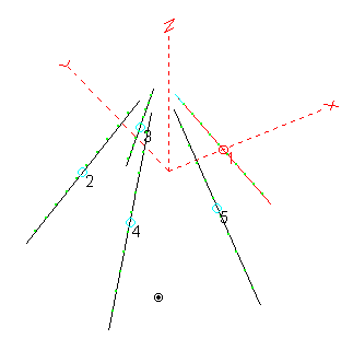
As I thumbed through the Antenna Book (18th edition, chapter 6. but the array appears in several editions), I noticed the 40 meter Sloper Array. The design, attributed to David, K1WA, uses 5 dipoles connected to the top of a tower (or any central support), and then sloping away from the tower. The dipoles are spaced evenly around the support, with 72 degrees between dipoles. The dipole angle with the ground is approximately 60 degrees. The antenna looks like a (large) wire Christmas Tree or inverted cone.
Each dipole is fed with a certain length of coax that comes to a central control box. One of the dipoles is connected to the radio. The other 4 cables are left open. Due to their length, they act as inductors at the dipole feed points, which creates a parasitic reflector. So, there is one driven element and 4 reflectors. Through the use of 4 relays, the 5 different directions can be selected.
The design presented was suggested for 40 meters. With a single central support at least 70 feet tall you had an antenna system with gain and directivity, and it could be electrically steered in five directions. I was impressed with the simplicity of the design, and how it was possible to have directivity and direction switching for a fraction of the cost of a traditional 40 meter Yagi, rotator, and tower to support the rotator and antenna. This is not to say that the Sloper Array is as good as a Yagi, but both do have directivity and gain, and the Sloper Array performs much more like a Yagi as compared to a dipole or inverted Vee. There are other directional antennas with gain for 40 meters, such as the classic Bobtail Curtain, but these were nearly impossible to rotate, so you have to either accept a subset of all directions, or build several antennas.
Around the same time, I purchased a copy of the EZNEC antenna modeling and simulation software. One of my first models was the Sloper Array, and I seemed to be able to make it work. The only hard part was computing the coordinates of the end points of the 5 dipoles. But, that was simple trigonometry. With the model, I could experiment with the angle of the dipoles, and the length of the transmission lines, and watch the performance change. This was all very interesting stuff, especially seeing as when I got into the hobby in 1969, there was much subjective talk about antennas, but very little objective data.
I eventually built a Sloper Array, cut for 20 meters, as opposed to 40. The 20 meter version was short enough that I could build a center support out of wood, which kept the whole project inexpensive.
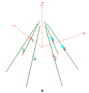
As part of researching the Sloper Array, and talking about the one I built, I met Grant, K7GT. Grant was way out in front of me on the design, and he mentioned that there was a variation of the Sloper Array that used 6 dipoles, as opposed to 5. In this variation, two opposite dipoles were considered to be the driven elements, and were connected to the feedline back to the radio. Two of the dipoles to one side of the center line had their transmission lines shorted, and the remaining two dipoles had their transmission lines left open. In one case, the stubs provided capacitive reactance, and in the other, inductive reactance. This turned two dipoles into parasitic directors, and two into parasitic reflectors.
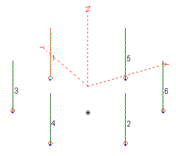
While modeling suggested that this variation did indeed offer improved performance over the 5 dipole version, the incremental improvement seemed not to be worth the extra work. My guess was that the fact that the dipoles were not parallel to each other negated some of the benefit of the inherent design. All 6 dipoles do come quite close together at the top of the array. I changed the design from 6 center sloping dipoles into 6 verticals, and the relative performance jumped higher. In the back of my brain I was left with the idea that there was a 6 element design that had two reflectors, two center, and two director verticals, and it could be stepped in 6 directions. The elements were located at the corners of a hexagon.
Here are a few drawings.
 |
 |
 |
| Original 5-Dipole Sloper Array | 6-Dipole Variation | 6-Element Hex Array |
The left picture is the original Sloper Array. Dipole #1 is the driven dipole, and the remaining 4 dipoles act as reflectors due to the open stubs at their feedpoints. The array fires along the positive X axis. The middle picture is K7GT's variation. Assume dipoles #1 and #2 are fed. Some sort of matching network is needed to match to 50 Ohms, but that is not part of this picture. If dipoles #3 and #4 have open stubs, they will become reflectors, due to inductive loading. At the same time, Dipoles #5 and #6 have shorted stubs, which turn then into directors. This array will also fire along the positive X axis. It has 6 directions, as opposed to 5 with the original Sloper Array. The array on the right results from replacing the sloping dipoles with 1/4 wavelength verticals. Performance is best when the feed system is converted from parasitic to all-driven. The relative current magnitudes from reflector to middle to director elements are 1 : 2 : 1, and the phase difference is approximately +120 : 0 : -120 degrees, and depends upon the frequency and the desired pattern. This is the antenna that was constructed and is described on these pages.
As some time passed, my main area of interest seemed to center on the lower bands, 160, 80, and 40 meters. DX was harder to work on these bands, and the challenge there was in fighting the noise and trying to wrestle with unpredictable propagation, not being a little louder than the other 500 stations calling the DX on 20 meters. I had already started to use verticals, which worked quite well at my location. My explanation for that good performance was the ability to have a large radial system which was located over my septic tank leech field, with midwestern farm soil, and a lack of buildings and power lines around the antenna. Although I was happy with the verticals for transmitting, they did not seem to be as effective on receiving. In particular, I developed the sense that stations could hear me better than I could hear them. I like the description of being an alligator, from the DXing on the Edge - The Thrill of 160 Meters book. An alligator has small ears (poor reception) but a big mouth (lots of transmission). This is not a good situation. It's better to have large ears, at least as big as your mouth.
Even with 5 acres, I still did not have the room for the classic Beverage antenna, an excellent receiving antenna. I did try some shorter Beverages, but they just didn't work well enough to justify the wires running all over the place at head height (even over the winter season). As I read more and more, I built loop antennas, K9AY's, and Flags. This led to both end-fire and broadside arrays of these antennas. All along the way, my reception performance continued to improve. What I should say is that my reception performance in selected directions improved. In some cases, I had fixed arrays, usually pointed at Europe. While these antennas proved various concepts, they did not provide a station with coverage in all directions.
One fact common to those receiving antennas was that they all had very low gain, perhaps 20 to 30 dB lower than a full-size vertical with good efficiency. In general, it was worth it to give up the gain in favor of directivity. I could listen to DX 365 days a year. After all, if you can hear background noise in your receiver, additional gain is not needed. The truth was, however, that the bands (especially 160 meters) were usually most active during the quiet times of year, over our winter season. This was not surprising, since the high noise level kept many hams off of the bands. This was a rich irony. I had antennas that could hear stations, if only the stations would get on the air. While my receiving antennas, with their high directivity but low gain, would work well over the whole year, the (casual) operators came out mainly during the short low-noise season, when the noise problem was minimized. When the atmospheric noise is naturally lower, it becomes worth it to pursue gain over directivity. In fact, during the lower noise winter, the best antenna was often times my otherwise noisy vertical.
What I really wanted was my cake, and to eat it to. I wanted directivity and gain.
I should fill in some details, in case they are not obvious. I mention my septic tank leech field since that adds moisture to the soil, and moisture improves soil conductivity, which improves the efficiency of verticals (by reducing ground loss). The leech field is 1200 feet of perforated plastic pipe surrounded by gravel, buried around 2 feet below the surface. All of the house waste water is pumped through the field. The field is actually headed by a manifold which distributes the water across a parallel set of pipes, spaced by several feet. The idea is to evenly distribute the waste water across the greatest area. I don't really know if this additional moisture helps the verticals, but I can't believe it hurts. On top of that, the soil in my area, according to the table in the ARRL Antenna Book, rates near the top of the conductivity scale (Ohio, pastoral, low hills, rich soil, 0.01 S/m).
What's a good antenna? Depends. Depends upon what you are trying to do with it. One could argue that the cost of the antenna matters, and whether it can fit on your property. There are many factors to be weighed and considered.
I find myself considering something called RDF, the receiving directivity factor. This is the maximum antenna gain minus the average gain, and expresses the average advantage that the primary direction has over all other directions. Since the lower bands tend to be characterized as having substantial background noise, which can come from many directions, the RDF is a meaningful metric when evaluating performance on receiving.
Gain is clearly related to RDF, since positive antenna gain in some direction is only obtained by negative gain in some other direction. You can't gain an advantage in some direction unless you give up an advantage in some other direction. That's why we rotate certain antennas, in order to select who gets the advantage.
Directivity is important to both RDF and gain. We can improve both reception (RDF) and transmission (gain) by making the antenna response pattern as narrow as possible. The only problem left is that we need to be able to orient the antenna in all useful directions and elevations. That can be a big problem.
Directivity comes from cooperatively combining radiating elements. The combination reinforces in some directions, and cancels in some directions. The elements must be spaced over some physical distance so that they can form the aperture necessary to focus the signal at a far away point. Stated simplistically, in order to improve the signal strength at some distance, we need to build our antenna system out of more elements spaced further apart, assuming a correct element combination. This is a long winded way of saying that good (high gain, high directivity) antennas take up space (well more space than lower gain antennas).
The best way for me to have both gain and directivity was to build an array of full-size phased verticals (if I couldn't put up a full-size Yagi at 150 feet!). The array should have a relatively high RDF for reception. The constraint of size began to dominate the thinking. Ideally, whatever I would build should take up a little less than 1 square acre, that is, 200 feet by 200 feet. This was the area right over the septic tank leech field, an area that was unused field space, and set apart from the 160 meter vertical, the tower with my Sommer beam, and the other receiving antennas. Whatever was going to happen on this space was going to be my 80 meter and 40 meter transmitting solution, since the space was previously used by an 80/40 meter vertical. Because I already had a 160 meter vertical, it was not essential that this new antenna work on 160 meters. Still if it could be used for improved 160 meters reception, that would be a great bonus.
Several sources suggested that the 4-Square offered reception performance similar to a two-wavelength Beverage. The 4-Square has a main lobe with a 3 dB beamwidth of around 90 to 100 degrees. On top of that, the antenna normally is not a multiband antenna. Some sources suggested that you could interlace 4-Squares, but it was best to skip bands. In other words, don't interlace (or co-locate) two adjacent amateur bands. Well, I wanted to interlace 80 and 40 meters, which were adjacent bands (60 meters doesn't count!). I was also bothered by the fact that if I nested two 4-Squares, I would have 8 elements, but only use 4 at a time on a single band. Seemed wasteful.
So, I asked myself if I could do better than the 4-Square? Could I get a higher RDF, and possibly create a multiband antenna?
What came to mind was the 6-element hex array which was conceptually based upon the 5-element 40 meter Sloper Array.
Modeling suggested that by varying the phasing between the elements you could get 80 and 40 meters to share the same spacing, and that the pattern would narrow towards 60 degrees on 40 meters. The RDF improved over the 4-Square, from 10.42 to over 12 dB (depending on the band). I felt that this was a meaningful improvement, given the small useful range of RDF. Several people have asked me: why did you go to the work of your 6-element hex array as opposed to the popular 4-Square? There are three reasons. One, to be different. Two, to achieve multiple band operation. Three, to improve the RDF over a 4-Square. Note: improved gain is not on that list. While there may be a dB or so more gain with the hex array over a 4-Square, who cares? That amount of gain can be lost in the details of ground radial efficiency and feed system efficiency. By the way, I prefer ground mounted radials, 60 of them per element. In the end, it's almost 2 miles of radial wire.
As a final bonus, the modeled array appeared to offer a good pattern on 160 meters, if I could create a feed system to deal with the short elements, and the problems created by short elements (low resistance, high reactance). It was clear from the start, however, that it would be impossible to achieve any sort of efficiency on 160 meters, so the array would only be used for reception. This was fine, however, since I had a transmitting vertical for 160 meters.
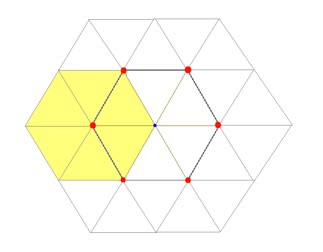
I spent some time playing with the size of the antenna array. There was really only one defining dimension to the antenna array. That is the spacing from the center to an element, which is also the element to element spacing, which is also the length of the radials. This relationship follows from the definition of a hexagon. I ended up with 40 foot spacing. Larger spacing would improve 80 meter performance, but 40 meter performance would start to suffer (yes, spacing can be too large), and I would take up more ground space than I had available.
 |
| Hex Array Cell View (Looking down from above) |
In the cell view, each line segment is equal to 40 feet. The red circles are vertical elements. The center is a blue circle. The phasing networks and directional control are located at the center. The 6 yellow segments represent the radial field for a single vertical. The outer 1/3 of the radial field for each vertical is unique to that element. The remaining 2/3 of the radial field overlaps adjacent elements, 1/3 to the clockwise element, and 1/3 to the counterclockwise element. The longest distance across the array is 4 line segments, or 160 feet (left to right). The shortest distance across the array (top to bottom) is 138.5 feet (COSINE (30) X 160).
The last major issue was the implementation of each of the six elements. My previous vertical was the MFJ-1792 40/80 meter vertical. This is a very good antenna, since it is full-size on 40 meters, and top-loaded on 80 meters. Should I just buy 5 more? As part of the being different theme, I decided to create my own 40/80 meter vertical. The design is the typical trap design, using a coaxial cable trap. Perhaps the novel part of the design is mechanical, with a single guying point and how I can raise and lower them by myself. I do believe that the antenna should have improved gain (efficiency) and especially bandwidth over the MFJ-1792.
What was fuzzy in my plans was the phasing networks/feed system. I left that as part of the details. Well, this was quite an oversight on my part. In the end, the hard part of the project was the feed system. But, it's also where most of the learning, fun, and frustration took place.
I set out to build a 6-element array of 80/40 meter trap verticals. The verticals would be located at the corners of a hexagon that had 40 foot spacing between the elements and the center. The array would be used for transmission and reception on 80 and 40 meters, and possibly reception on 160 meters. Each vertical would have 60 ground-mounted radials, 40 feet long. The array has a diameter of 160 feet (at the perimeter of the radials).
Back to my Experimentation Page