 |
| Figure 1: Control Box Architecture |
Greg Ordy
This page describes the control and switching system which selects the band and direction of the array. Unlike other pages which focus on analog electronics, this page contains the digital content of the system. The control and switching system is located at the physical center of the array. It's based around a Rabbit microprocessor that controls 12 DPDT relays that perform the needed switching through two logical matrices. The microprocessor was used for two main reasons. First, it allowed the use of a 4-wire control cable back to the station. Since I already had a buried cable in place, the number of available control wires was fixed, and there were not enough discrete wires to allow remote operation of all relays. Even if it were possible to run all of the wires back to the station, that begs the question: what do you do with all of the wires once you get there?
Although this array can only fire in 6 different directions, in my mind I wanted a rotator-like interface. This suggested a software-based solution, where I could write a program with as much eye candy as desired. Once on the computer, the most natural way out of the computer is via an RS-232 serial interface. The actual remote control of the array is accomplished by sending serial commands over a single RS-232 wire that the microprocessor interprets and uses to set the relays. Status and completion information come back from the microprocessor to the computer on a second wire. The remaining two wires are ground, and +24 VDC. So, the second reason for the use of the microprocessor was to allow me to write a software-based control box that communicated with the array via RS-232 ASCII messages.
The total connection between the array and the station is a single coaxial cable, and the 4-wire control cable. The coaxial cable does support the Ameritron RCS-4 remote coax switch. This is the final band select switch located near the array.
There were parts of this project that were more work than anticipated, such as the phasing networks. Some parts, however, such as this control and switching system, were actually much less work than anticipated. The particular microprocessor I selected came bundled with a development board with ample space for the interface circuits, and a companion C language compiler for software development. That made the digital part very simple and a lot of fun.
Here are a few block diagrams that will hopefully explain how the control system is put together.
|
| Figure 1: Control Box Architecture |
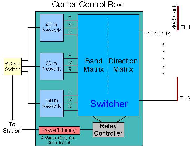
The Control Box sits at the physical center of the array. It contains all of the functional units shown on the green background. The boxes include:
Power/Filtering: Accepts the 4-wire cable that runs back to the house. The signals are all filtered and bypassed to reduce interference, and provide protection against lightning/static damage. A 3-terminal voltage regulator provides +5 VDC for the digital logic board.
Relay Controller: The relay controller consists of the Rabbit development board, which includes the microprocessor and the circuitry to drive the relays.
Switcher: Direction Matrix: The relays that select the array direction by combining pairs of elements according to the overall array design. The outputs of the direction matrix are the forward, middle, and rear legs. 6 antenna inputs, 3 leg outputs.
Switcher: Band Matrix: The relays that take the three legs from the direction matrix and select the correct band phasing network. 3 leg inputs, 9 network outputs.
40 m Network: The 40 meter phasing network. All of the phasing networks have 4 coax connectors, which are the connection to the station, and the 3 legs (F, M, R).
80 m Network: The 80 meter phasing network.
160 m Network: The 160 meter phasing network.
RCS-4 Switch: The remote portion of the Ameritron RCS-4 remote coax switch. The box is located about 50 feet away from the Center Control Box. The box existed long before the array was built, and was initially used to pick between several verticals in the area. It it still used to select my 160 meter vertical in the remaining position.
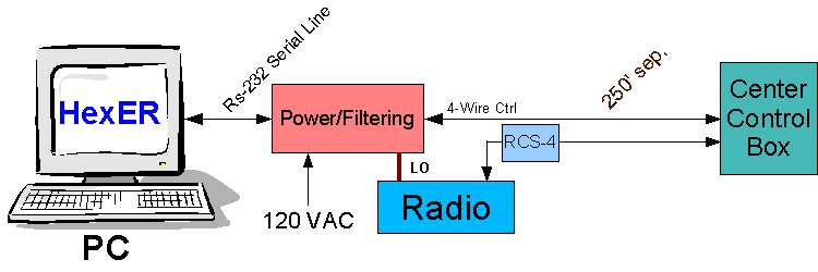
The Center Control Box connects to the rest of the system through a coaxial cable and a 4-wire control cable. The remainder of the system is located inside the shack, and has the following block diagram.
 |
| Figure 2: System Block Diagram |
PC: Nothing too special here, just a PC-compatible computer. An RS-232 serial port is needed to communicate with the array. Serial ports are becoming more uncommon. PCs once had at least two serial ports, but now usually have one. I have an internal board with 4 serial ports, so I actually have 5 total ports. 4 of the 5 are in use, with connections to radios, and packet modems, and all sorts of devices. Perhaps some day all of this will convert to USB.
HexER: The software that controls the array. My software rotator control box.
Power/Filtering: Similar to the power/filtering box at the array. The 120 VAC house voltage is transformed to a value around 26 volts DC. The is the line that provides power for the array. While the desired voltage at the array is near 24 volts, the supply voltage is somewhat higher to compensate for any voltage drop on the 250 foot run to the array. The RS-232 signals are heavily bypassed to reduce interference and provide lightning/static protection. The RS-232 signals go through an additional layer of active buffering to protect the computer from damage.
LO: Transmitter Lock-Out. It's desirable to remove power from relay contacts while they are changing state to avoid hot switching, which can damage a relay, and shorten its life. The power/filtering box includes a small relay which is under the control of the computer. Whenever the computer does not believe that the relays at the array are stable, it will open a set of contacts. These contacts are wired in series with my amplifier keying line. This means that I cannot key my amp when the array is changing directions. The relays are unstable after a direction changing command is send to the array. The microprocessor is programmed with the relay closing times. When it receives a command, it changes the relays, then waits the amount of time that the relays need to change state, then it sends a confirmation back to the computer. When the computer receives the reply command, it then enables the amplifier again. All of this takes several dozen milliseconds, so it is very fast in human terms.
RCS-4 Control Box: The control portion of the Ameritron RCS-4 remote coax switch. A low-level control voltage is added to the transmission line. This control signal operates the relays in the remote RCS-4 box and selects one of four antennas.
The distance between the station and the array is approximately 250 feet. Almost all of the cable run is made underground.
My biggest concern coming into this phase of the project was interference between the digital and analog circuits, and damage to either due to lightning or static discharge. 1500 watts of transmitting power are going to have to come within inches of a digital microprocessor, and it's low level signals. Will that upset the digital circuitry? The digital microprocessor is chock full of square wave signals rich in harmonics at frequencies all over the shortwave bands. Would my receiver be nothing more than birdies and chirps? Would a nearby lightning strike, or accumulation of static charge destroy the microprocessor, or the computer on the station side?
The only response to these concerns was to use as much shielding, bypassing, filtering, and decoupling as possible.
The serial line that connects the computer to the station-side power/filtering box is wrapped around a ferrite rod. The power/filtering box has back-to-back RS-232 drivers so that the computer signals do not go further than the box. The signal lines go through RF chokes, and are grounded with 0.001 uf capacitors.
At the array, the 4-Wire cable is wound around an iron core, and the lines again go through RF chokes and are grounded with 0.001 uf capacitors. The signal lines also have MOV protection.
The microprocessor board has bypassing capacitors on all relay control lines. The board is located in a nearly sealed metal case, where the control signal come out on a ribbon cable, through a small slit.
The digital and RF worlds must come together at the relays. The relay contacts switch RF, and the coil energizing voltage comes from the microprocessor board. In this part of the circuit I tried to keep the wiring short, and wherever possible, the digital signals are run perpendicular to the analog signals.
I'm happy to report that I've never detected any problems, interference, or failure. I don't know if I have a large safety margin, or a small one. Whatever it is, it is sufficient, and I don't regret any of my paranoia over potential problems with interference. The RS-232 signals on both ends of the line go into socketed Maxim MAX232 chips. My best guess is that these are the weakest link in the system, and if anything will blow out, they will. I have a number of them in the junk box, and I'm ready to go if one blows up.
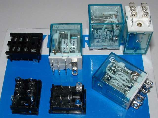
Sizing relays for RF applications can be a difficult process, and I'm the first to admit that I don't know how to do it correctly. There are current issues, voltage issues, and frequency issues. From past projects, I had found myself using a particular relay over and over again, without ever having any problems. The relay is made by Potter & Brumfield, and is sold by Radio Shack (I believe it's their part 275-218). This DPDT (double-pole double-throw) relay has 10 amp contacts, and a 12 VDC coil. I've used this relay in my Sloper Array, and 40 Meter Phased Delta Loop Array, as well as many other applications. I've pumped 1500 watts through it without problem. The relay is enclosed in a plastic case, so the contacts are not directly exposed to the weather. I usually use a dab of caulk to glue the top of the relay case to my enclosure and wire directly to the contacts.
A casual consideration of the switching needs suggested that I would use 10 to 20 relays, perhaps more if I got fancy and located relays at the base of each element, as well as the center control box. In order to reduce the cost of the relays, I looked around for an alternative, but similar, part. I ended up selecting the Rayex LB2-24DS relay, which I obtained from Jameco. This relay has the same size and pin configuration as the Potter & Brumfield part, similar contact rating, but uses a 24 VDC coil.
I normally use relays with 12 VDC coils, but since I had so many relays in this project, I wanted to reduce the current demand going out to the center control box from the house. By switching to 24 VDC relay coils, the current drops approximately in half (for a similar relay). I bought the relays in quantity, which reduced their price to about half of the single unit price of the Potter & Brumfield part at Radio Shack.
Another design goal was that I wanted to use a single relay part number for all relays in the array. This was to simplify purchasing parts, and to simplify maintenance Every relay can be swapped with every other relay. In some cases I can use the DPDT feature as part of the design. When a SPDT relay is needed, I can use both contact pairs in parallel, increasing my power rating.
My next decision was to use relay sockets.
I've heard that this is a bad idea, especially at RF frequencies. A socket is also a place where corrosion and dirt can enter the picture, and cause problems. On the other hand, a socket makes it easy to replace a relay. My worst fear was that a relay would fail in the middle of winter, and I would have to take apart the control box with two feet of snow on the ground, bring it back into the house, and replace a part soldered into a small rat's nest of wires. Sockets would make it possible to painlessly change a relay in a minute. It's also true that not all relays will be used and abused in the same way. With relays in sockets, I could even rotate my relays, like tires on a car, in order to get even wear on each part.
With all of the pros and cons considered, I decided to use sockets.
So far, with the relays outside for over a year (November, 2003), there have not been any problems that I can tell due to the use of sockets. I have pulled relays and checked their pins, and all are still shiny and bright, with no signs of RF pitting, or weather corrosion.
Here is a picture of the relays and the sockets. Please click on the picture for a larger view.
 |
| Relays and Sockets |
The nominal coil resistance for the 24 VDC coil relay is 650 Ohms. That makes the relay current 37 mA, and the power needed to keep a relay closed is approximately 0.89 watts.
When I first dreamed about my array, I envisioned all sorts of combinations and permutations. I would have my basic hex array, but why not have a mode where I could just drive one vertical, for omni-directional coverage? Why not have a mode where I could drive 2 elements in a broadside pattern? On paper, all of these permutations are possible, but the truth is that it would require a lot of extra parts to switch all of the needed components in and out of the circuit. In some of these cases, it would be necessary to locate relays at the base of the vertical elements. This would be needed when it was desired to float a vertical so that it would not contribute to the radiation pattern. It doesn't take long to end up with a large number of relays and other phasing network parts.
In the end, I was satisfied to support my basic Hex Array design - no more, no less.
The switching breaks down into two logical groups, the direction matrix, and the band matrix. The 6 verticals are combined in pairs to create 3 legs. The direction matrix provides this switching. Once we have 3 legs, they must be routed to the correct phasing network - either 40, 80, or 160 meters. This is the job of the band matrix.
Let's start with a simple approach to the direction matrix. Each element must connect to the front (director), middle (center), or rear (reflector) leg depending upon the direction of the array. Two relays can be wired in series to provide a three-way switch. So, the most direct approach would be to use two relays for each element, and have each relay pair pick one of the three legs. This arrangement is functionally correct, and would require 12 relays. This design has permutations which are not needed. Any number of elements can be connected to any of the legs, which is a capability that we don't need. For a given direction, we need two elements to connect to each of the legs, no more, no less.
The question becomes, can the desired switching be done in less than 12 relays? Consider the following diagram of the elements.
 |
| Element Diagram |
In this orientation, elements 1 and 4 form the middle leg, elements 2 and 3 form the front leg, and elements 5 and 6 form the rear leg. If we wanted to reverse the direction of the array, elements 1 and 4 would remain the middle leg, and the role of elements 2 and 3 and elements 5 and 6 reverse. In fact, elements 1 and 4, opposite elements, are the middle elements in two of the six directions. If we step the array clockwise by 60 degrees, elements 2 and 5 become the middle elements, and will remain the middle elements if the direction is flipped 180 degrees. With one more step of the array we see that elements 3 and 6 are now the middle elements for two directions. So, the three pairs of opposite elements have the property that each is the middle leg for two of the six directions. If we bring each pair into the poles of a DPDT relay, we can activate that relay to dump them onto a middle bus (or leg), and when the relay is not energized, the two elements will pass though the relay to the next level. This seems like a starting point worth investigating.
Here is the schematic of the direction matrix. The three relays I just described are relays K1, K2, and K3.
 |
| Direction Matrix (+24 VDC label missing from lower left connector) |
Relay K1 accepts elements 1 and 4, each going to a pole. If the relay is energized, both elements are connected to the D or middle leg. Relay K2 handles elements 2 and 5. Relay K3 handles elements 3 and 6. Exactly one relay should be selected at a time.
Ok, that handles the middle leg, but we still have two legs to go.
Looking again at the element diagram, we can see that when a pair of opposite elements are not being used as the middle leg, one is part of the front leg, and the other is part of the rear leg. This suggests that a second relay can be used to connect one of the opposite elements from the first relay to the front leg, and the other to the rear leg. When that second relay is energized, the two element must swap legs. This is the function of relays K4, K5, and K6. They determine the elements connected to the front and rear legs.
As the relays are shown on the schematic, when only K1 is energized, elements 1 and 4 are the middle leg, elements 2 and 3 are the front leg, and elements 5 and 6 are the rear leg. To reverse the direction of the array, energize K5 and K6. By selecting one of K1, K2 or K3, and then controlling the pair of K4, K5, and K6 which is not directly to the right of the selected K1, K2, or K3, you can pick all six directions of the the array.
This scheme requires 6 DPDT relays as opposed the simple and direct approach which uses 12 relays. The 12 relay version can create many additional combinations, but they are not useful, so there is no value in having them available. The 6 relay version is constrained to what we need, and nothing more.
PA0 through PA5 are the designations of the microprocessor control signals used to control the relays. The diodes are type 1N4001, and the capacitors are 0.01 uF.
The band matrix is very simply. We need to take a leg and route it to one of the three band phasing networks. A single SPDT relay is a two-way switch. When you add a second SPDT relay in series with the first relay you have a three-way switch. It takes two relays. therefore, to make one three-way switch. Since I have 3 legs, the band switching matrix requires 6 relays. Although a SPDT relay is all that's needed, I used my standard DPDT relay, and routed the signal through both poles.
Since all of the legs switch to the same band at the same time, the 6 relays can be controlled with two signals - each signal controlling three relays. Here is the schematic.
 |
| Band Matrix |
As in the case of the direction matrix, the signal designations are D, F, and R for the middle (driven), front (director), and rear (reflector) legs. The labels 40, 80, and 160 signify the band.
Since 80 meters was my target band, I wired the relays so that the legs were routed to the 80 meter network when no relays were energized. If you turn on relays K1, K2, and K3 (via PA7), the 40 meter network is selected. If you turn off K1, K2, and K3, and turn on K4, K5, and K6 (via PA6), the 160 meter network is selected. Turning on all of the relays doesn't make much sense, since 40 meters will be selected in the first set of relays (K1, K2, K3), and the remaining three relays just don't matter.
PA6 and PA7 are the designations of the microprocessor control signals used to control the relays. The diodes are type 1N4001, and the capacitors are 0.01 uF.
The direction and band matrices require a total of 8 control lines. To activate the relays on the line, the line is pulled down towards zero volts. The driver circuit is shown in the microprocessor board section. Although there are 12 relays, never more than 6 are energized at a time.
The station-side power/filtering schematic is shown in the following picture.
 |
| Station Buffer Box Schematic Diagram |
The bridge rectifier and associated filter capacitor generates a DC voltage level a little above 24 volts. This is the supply voltage for the array. Within the box, an LM350 regulator creates +5 VDC which powers the Maxim 232 chip and the transmit lockout relay circuitry. The overall circuit is built into a small box which sits under my station desk. Since the LM350 is dropping 24 volts down to 5 volts, it does get very warm to the touch. Much of the inside volume of the box is taken up by a heatsink for the LM350 made from aluminum angle stock. Here are pictures of the box contents, and the front panel of the box. Please click on a picture for a larger view.
 |
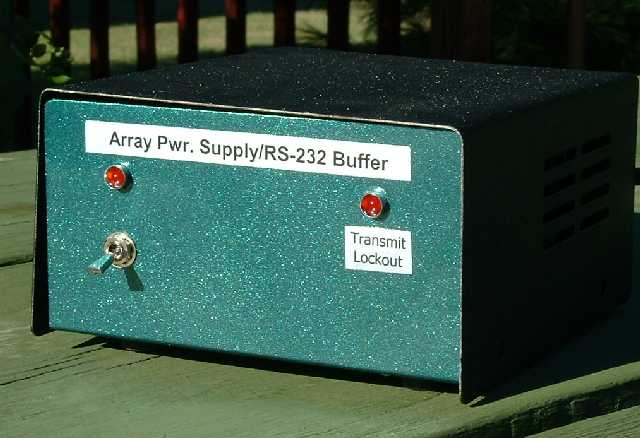 |
| Station Buffer Box Contents | Station Buffer Box Front Panel |
The Maxim 232 chip functions as an isolation buffer between the PC serial port and array. Noise or spikes will hopefully be filtered by the RF chokes and bypass capacitors, but if a spike should get past those parts, it should destroy the 232 chip before it destroys the serial port in the PC.
The power/filtering box at the array consists of similar serial signal filtering an a second LM350 regulator which generates the +5 VDC for the microprocessor.
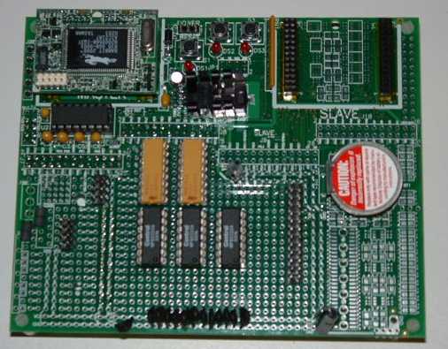
The microprocessor board I used is the standard development/evaluation board which is based upon the Rabbit 2300 CPU. The board has an unpopulated wiring area which I used to hold the relay drivers. I purchased a development kit which included the board and a C language development system. I wrote the embedded code on my PC, where it was compiled and downloaded to the board while it sat on the desk. The development system comes with a serial cable that attaches between the board and the PC. You can debug the software through the cable, as well as download it. It is a very powerful environment for developing embedded applications. The program is saved in flash memory, so turn around cycles are nearly instantaneous (no EPROM erasing and burning).
Each relay is driven by a single transistor which sinks the relay current. The following pictures show the board and the driver schematic.
 |
 |
| Rabbit 2300 Evaluation Board | Relay Driver |
Wiring was simplified by using resistors in DIP (dual inline package) packages, and quad transistors also in DIPs. Wire wrap construction was used. The relay driver components are visible in the lower middle part of the board. The relay signals are carried on a ribbon cable out of the back of the box through a small slit.
One feature of the board is that it includes several pushbuttons and LEDs which are available to the microprocessor. I programmed one pushbutton to put the microprocessor into self-test mode, where the relays are turned on an off in a sequential pattern. A second pushbutton takes the array through all 18 combinations, that is, 6 directions for 3 different bands. When the array is at a home position, one of the LEDs is turned on. This feature lets me control the array completely from the center control point, and that was very useful when testing the directional symmetry of the array.
Normally, the array is controlled from inside the shack, using the HexER program which is described a little further down this page. The control protocol is very simple, and consists of two characters which encodes the desired band and direction. The command is sent from the computer to the microprocessor. It replies with an acknowledgement character. The command set includes the self-test mode.
You have to be a little careful when evaluating the I/O capabilities of the microprocessor. While it has a large number of functions, such as parallel I/O, serial I/O, and intelligent peripheral I/O, these functions share a limited number of pins. If you use a serial I/O port, it may reduce the number of parallel I/O pins. In my case, I needed a single serial port, and all of the rest of the pins are devoted to parallel I/O. There are a number of pins which are unused, and I could add additional control functions to the existing board very easily.
The microprocessor board requires a 5 VDC supply at approximately 100 mA. This is a power consumption of 0.5 watts. An energized relay dissipates around 1 watt. Assuming all 12 relays were closed, which does not happen in normal operation, the power consumed by the control box is approximately 13 watts. As explained in a previous section, at most 6 of the 12 relays are energized, so the power consumption is closer to 7 watts.
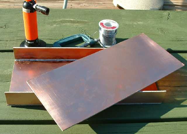
It always seems to be a chore to find the right enclosure for a project. The only positive aspect of this project enclosure was that I didn't care what it looked like. I was only interested in function, not form. My junk box included a number of very thick double-sided printed circuit boards that I picked up from the local surplus store. These boards are very thick, and heavy. They are 1/8" thick, and each blank board is a square, 14" on a side. I decided to make my own boxes by cutting pieces to size, and soldering all of the seams. The boards were so thick and heavy that I had to use my torch to have enough heat to solder the pieces together.
I made up two types of enclosures. The first was the relay mounting box, which includes all of the female panel-mounted coax connectors, and a side box to hold the microprocessor board. The second unit was the box to hold a phasing network. I made up three of these boxes, one for 40, 80, and 160 meters. The boxes are related in that they are all mounted on a single piece of plywood. The plywood is mounted inside a larger plastic box, and that box is mounted to the 4" X 4" post at the center of the array. All of the PC-board boxes are 14" wide, which is the uncut length of the PC board material.
When a joint must be taken apart, I used aluminum angle stock to create corners which trap panels in place. The aluminum angle was attached to the PC board with stainless steel hardware.
Here are some pictures of the enclosures. Please click on a picture for a larger view.
 |
 |
 |
| Basic Box Construction | Relay Mounting Box/Microprocessor | Phasing Network Box |
Box assembly was aided by the use of clamps to hold panels at right angles to each other while soldering a seam. Before assembly I used steel wool to remove all tarnish from the boards. When a box was complete, I covered it with several light coats of clear spray acrylic paint to reduce future tarnish and oxidation.
The middle picture shows the guts of the control box. The six connectors on the left edge of the panel are the six antenna inputs. The nine connectors on the top edge are the connections that go to the phasing networks, three per band, three bands. The 12 relay sockets are mounted in rectangular cutouts in the top board. Making these holes was the time consuming part of the operation, since I had to drill round holes in the center of the rectangles, then switch to a saber saw to get close to the desired shape, and finish with a file so that the relay socket snapped snugly in the hole. The microprocessor board is on the right. The board floats on spacers located at the corners. The relay control signals are carried on the ribbon cable which exits through a slot on the back of the microprocessor box. Power and serial communications lines come in through a small hole in the front right corner of the microprocessor box. A cover goes over the box, creating a sealed metal box around the microprocessor board, except for the ribbon cable slit and the power/communications hole.
The phasing box is shown on the right. A three inch diameter toroid is lying in the box to give a sense of size and proportion. The cover is not part of the picture, and it slides under the aluminum angles on the corners, trapped above the top edge of the PC boards. The 4 coax connectors represent the network connection to the radio, and the three signal legs. The small hole on the right side of the panel holding the connectors is for future expansion. It would be used to mount a connector to allow relay control signals to enter the phasing network. This could be used, for example, to shift the network response from one portion of a band to another (by switching in and out different reactive components).
As long as I'm describing cheap enclosures, I might as well mention the outer plastic shell which holds the control box and the three phasing network boxes. A 4" X 4" pressure treated post is mounted at the physical center of the array. The top of this post is a guying point for each of the verticals. The plastic shell is mounted to the side of the post. The shell is nothing more than a large storage tote, which has a hinged lid, that becomes a hinged door in this application. The boxes are mounted to a plywood rectangle that is the size of the bottom of the tote. The plywood is held against the post with wing nuts, and the plastic tote is trapped between the plywood and the post. The network boxes are pinned to the plywood with a pair of studs screwed into plywood. The boxes can be taken out very easily by removing two nuts and unscrewing four coax cables. The boxes needed to come and go many times while I was building and adjusting the phasing networks.
A number of cables enter the plastic enclosure, and they do so via holes in the bottom. The cables include the 6 vertical feed lines, the feed line bundle (40, 80 and 160 meters) going to the remote coax switch, the power/data cable, and a ground wire. The center post has it's own radial system which connects into the 6 vertical radial systems. An 8 foot ground rod is also located at the center post. The ground rod and the radial system are connected to the ground wire that runs into the box. The ground wire runs to the control box, and the three phasing network boxes.
There are nine jumpers that connect the control box to the phasing network boxes. I used RG-303 Teflon-insulated coax for the jumpers to keep them thin and flexible, but able to carry the power load. The jumpers come in sets of three, one set for a given phasing network. The jumpers are cut to the minimum length necessary to span the distance from the control box to the phasing network. The jumpers should be kept as short as possible, since they will influence the electrical distance to the antennas. The electrical distance is a function of frequency, so I used the shortest jumpers for 7 MHz, and the longest jumpers for 1.8 MHz. The 40 meter jumpers are 12" long, the 80 meter jumpers are 18" long, and the 160 meter jumpers are 24" long. This means that the physically lowest phasing network in the enclosure is the 40 meter box, and the highest box is the 160 meter box.
Here are three pictures of the plastic box and the box contents. Please click on a picture for a larger view.
 |
 |
 |
| Center Control Box Enclosure | Control Box Contents | Microprocessor Box and Relays |
In the middle picture, the power/filtering circuitry is contained in the orange box mounted on the bottom of the plastic tote. The 80 and 160 meter jumpers are not shown in this picture. The right picture shows the microprocessor box and the relays as well as the associated coax connectors.
I do mow the area around the array, and that means that I have to disconnect the cables from the center box and move then out of the way every week or two during the summer. I don't want to drive over the cables with my tractor. Since it takes some time to remove and reattach the cables, I wish I had a better scheme which would let me mow but keep all of the cables connected. I can move the cables a few feet from side to side, and that would let me keep them connected, but then you waste time mowing in a pattern to avoid the cables - and I can always have a mowing accident. I really wish I had an underground feed to the elements, but I can no longer add that capability, since the ground is covered with 360 radials. The underground cable would need to be replaceable, which means that direct burial is not an option. In retrospect, I should have installed PVC pipe underground from the center control box to the elements. The pipe would need to be large enough to allow cables to be pulled through easily, probably at least 1 1/2 inches in diameter. In other words, if you need an underground feed, add it before you start laying down radials.
The program which I wrote to control the array is called HexER (Hex Array Electrical Rotator). Conceptually, the program is nothing more than an 18-way switch, selecting three bands, each with six directions. The eye candy part is to display the state of the array using an azimuthal-equidistant projection located over my location and highlighting the direction of the array as a pie-shaped wedge representing the 3 dB beamwidth of the antenna. The program can display several different maps on the window. The maps differ in the amount of the world that is shown. The program has 6 different maps. The maps, centered on my location, have radius values of 3,000, 4,000, 6,000, 8,000, 10,000, and 12,466 miles. When using the array, I pick a map depending up my target QSO location. By the way, the distance 12466 miles represents the distance to the furthest away point on the planet (antipode relative to my location). This shows all of the world.
Here is a screen capture of the program without a band or direction being selected, and the 12,466 mile radius map.
 |
| HexER without Band or Direction Selected |
In the next picture, I've set the band to 40 meters, and selected the 30 degree direction, which favors Europe. The 6,000 mile radius map is the background.
 |
| HexER, 40 meter band, 30 degree direction |
The beamwidth indication is programmable for each band. The values used come from EZNEC results.
The array direction can be selected using several different methods. You can use menu or toolbar commands, or, simply click on the map with the mouse, and the array direction will change to the closest fixed direction.
If the maps themselves look a little familiar, it may be because they came from the program GCM, by Roger, SM3GSJ. This popular program creates azimuthal-equidistant projection maps for a given location on the planet. I put in my location, and specified the different radius values. I captured the bitmaps directly from the screen using a capture program, and then pasted them into the software development tools. I experimented with the colors, and ended up with green earth, and gray water. This color scheme, combined with the highlighting of the 3 dB beamwidth, provided the look which I found most pleasing and easy to interpret.
HexER is written in the C++ language, using the Microsoft Version 6 Developer's Studio. The Window's programming uses the ATL/WTL libraries and approach.
The transmitter lock-out feature disables the amplifier when the antenna band/direction relays are changing direction and/or band. The lock-out is achieved by passing the amplifier keying line through a normally closed set of relay contacts. The relay, located in the station-side power/filtering box, is controlled by the computer through a modem control line available on the COM port that has the serial data lines. The HexER program is responsible for determining when the antenna relays are changing, and activating the lock-out relay during that period.
The time-out period begins when the user enters a new direction or band via HexER. HexER enables the lock-out, and sends the appropriate control command out to the array. The microprocessor in the control box decodes the command, and changes the relays. It delays an amount of time which is based upon the switching speed specification of the relays (15 ms). It then sends a command reply to the inside computer. When the computer decodes the reply, without error, the lock-out relay is turned off, which enables the linear amplifier.
At the normal transmission rate of 1200 baud, a single data character transfers in 8.3 ms. A direction changing command is 2 characters, and the reply is 1 character. Combined with the relay delay, the minimum lock-out time is 8.3 + 8.3 + 15 + 8.3 = 39.9 ms. I suspect that with other delays on the computer, the typical direction switching time is on the order of 50 to 100 ms. This means that the array can switch directions between 10 and 20 times per second. This is clearly much faster than needed for amateur radio purposes.
The control portion of this project went together quickly, and without problems. Concerns over possible interference between analog and digital signals were not realized. The Rabbit microprocessor made all of the software at the center box very easy to write. If you need to embed a microprocessor in some application, please consider this product line. It is a powerful family of parts with all of the contemporary peripheral circuits, and is very easy to program.
In practice, it has not turned out to be a problem to use a software-based rotator control program (HexER). There have been one or two times when I needed to reboot my computer while operating, and for that minute or so, I could not change directions or bands. This just has not been an issue. I may be one of the few hams who can say: please QRX for a minute while I reboot my rotator. Now that my computer can control my antenna array, some interesting experiments become possible. At some future point I would like to modify S Meter Lite to understand how to rotate the array, and program the software to log the background noise in all 6 directions in one session. It would record data for a few seconds in one direction, then switch to another direction and monitor them all in a round-robin fashion. This sort of data would show if the noise distribution was uniform or more directional. This is especially interesting at times such as sunset and sunrise.
Back to my Experimentation Page