Figure 1
Rotator cage with rotator and mast. |
Figure 2
Cage on tower plate, ready for antenna. |
Figure 3
Sommer XP-504 on mast, tower cranking vertical. |
Greg Ordy
Details, details, details. I selected the Sommer XP-504 antenna because it offered good performance on all amateur bands from 20 through 10 meters (and even 6 meters with an add-on kit). I chose the US Tower MA-550 because it was the right height, and had a low profile. I chose the Yaesu G-800SDX rotator because it had enough power to turn the antenna, a preset function, and an optional computer interface. All I had to do was bolt them all together - right?
Nothing is ever quite that simple.
The top of the free-standing MA-550 tubular crank-up tilt-over is a galvanized tube stub that is welded to a circular plate. The plate is approximately 6 inches in diameter. The plate is pre-drilled with radial slots to accommodate most any size and configuration rotator base.
The most straightforward implementation would be to bolt the plate to the rotator and use a short length of mast to connect the rotator to the Yagi boom mount.
This seemed like a very dangerous configuration because the rotator case would be the only mechanical support for the Yagi. A failure in the case would bring down the Yagi, in addition to the loss of the rotator.
To make matters worse, when the collapsed tower is tilted over, the entire weight of the Yagi would become a shear force across the rotator case, as opposed to a compression force when the tower is upright (ignoring wind). This seemed very unsafe, and I simply didn't want a failure in an overstrained rotator case to cause a perfectly good Yagi to come crashing to the ground.
In searching for a solution, two approaches emerged. The first was to simply get a very strong and massive rotator. Even with a substantially more expensive rotator, there was no guarantee that they were made to be the sole support of the mast and the antenna, and maintain that support while turned from vertical to horizontal.
The second solution turned into what I have come to call the rotator cage. I must credit Lonnie, NT6B, for giving me the direction I needed. According to Lonnie, folks have, from time to time, made support devices like this one. At the time I couldn't find any, so I made my own.
In the case of a normal triangular tower, the tower itself provides a structural cage that surrounds and supports the rotator. The rotator is usually located within the top section of the tower, a few feet from the top. This location allows the mast to travel through one or more thrust bearings that take the lateral forces, and even some of the mast and antenna weight. A failure in the rotator will simply keep the antenna from turning, it won't bring it to the ground.
In the extreme, one could simply bolt a tower section to the top of the tubular tower. Of course that would completely overload the wind and weight ratings, as well as create a large eyesore on top of an otherwise low profile installation.
My solution, the rotator cage, is a compact welded steel rectangle that performs the same function as a normal triangular tower. It transfers the load of the antenna directly to the tower, leaving the rotator free to simply rotate the antenna. A failure in the rotator case will not cause the antenna to fall.
The rotator cage is made from two square pieces of plate steel that are held parallel from each other by pieces of steel angle iron on all four corners. The plates are 1/4 inch in thickness, and measure approximately 10 inches by 10 inches. The angle iron corners are approximately 18 inches long, and are cut from 1 inch stock. At each angle iron/corner joint there is a weld. The bottom plate has holes that match the rotator bottom holes, which also fit in the slots on the tower mounting stub. The top plate was drilled to accommodate a Yaesu GS-065 thrust bearing (2 inch mast). The entire rotator cage was painted with several coats of rust inhibiting paint. The cage weighs approximately 20 pounds.
I tried to convince myself that this was the right project to justify getting into welding. In the end, I simply contracted a local metal shop to build the cage, based upon drawings that I made. The cost was approximately $75 (US$) in the 1998 time frame.
Another solution to this problem is to locate the rotator at the base of the tower. For this tower, the manufacturer does sell a version (MARB) where the rotator sits at the base and turns an inner shaft up to the top of the tower. This is an expensive alternative, however.
Here are some pictures of the rotator cage. You can select a picture for a larger view.
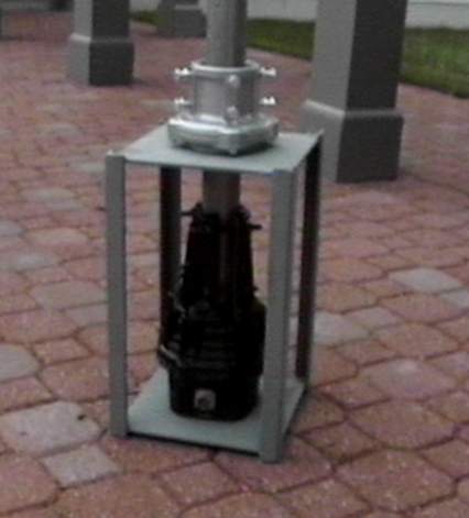
Figure 1
Rotator cage with rotator and mast. |
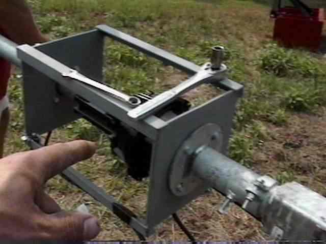
Figure 2
Cage on tower plate, ready for antenna. |
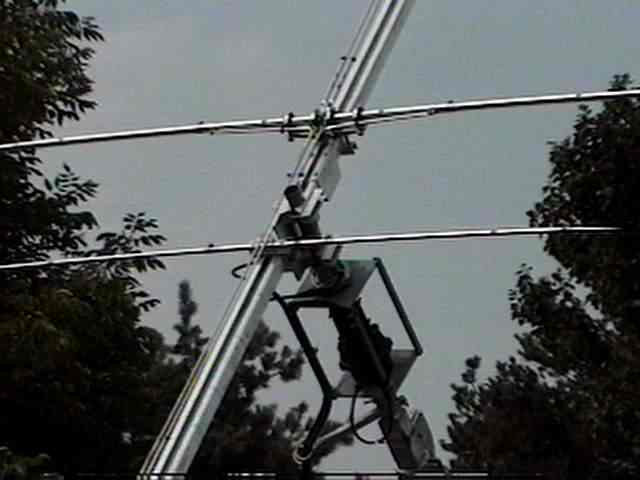
Figure 3
Sommer XP-504 on mast, tower cranking vertical. |
Figure 1 shows the rotator cage all ready for installation. The Yaesu rotator is within the cage. The thrust bearing is bolted to the cage top plate. A medium strength 2 inch mast extends from the rotator clam shell to about 8 inches above the thrust bearing. The entire mast is approximately 14 inches long.
In Figure 2, the cage is mounted on top of the tower plate. You can see the bolts that go from the bottom of the mount plate, through the plate, through the cage bottom plate, and finally into the rotator base.
After the cage was mounted to the tower, the antenna was mounted on the mast. One nice feature of using a crank-up tilt-over tower is that all antenna adjustments can be made while standing on the ground. In Figure 3, the tower is going from horizontal to vertical. The cage has very little visual impact, but adds substantial strength and is an insurance policy against undesired trouble.
In most normal (not telescoping) tower installations, it is common to attached, often with tape, the coax and rotator cables to the inside of the tower, at a number of points along the length of the tower. This provides ample support for the cables. With a crank-up tower, you cannot attach the cables to the tower since the sections telescope within each other. Most towers have, as either an optional accessory or standard part, stand-off arms that provide rigid support loops spaced about a foot away from the tower, one arm per section. The idea is that all cables can thread through the loops, and be kept away from the tower itself. On my US Tower the arms were optional, and I did purchase them.
For each loop you have to decide if you are going to fix the cables to the loop, or allow them to slide freely through the loop. If you attach the cables firmly to the loops, you will have more mechanical support for the cables, but when you lower the tower, and the arms become very close (since the sections have telescoped together), you will have created several cable loops which could get tangled together when you raise the tower. In addition, the cables will gather at the end (top) of the tower, since that's where the arms are - at the tops of the telescoping sections (this assumes you have a tilt-over base). In my case, I chose to let the cables slide through the stand-off arm loops. This means that the cables will gather at the base of the tower as it is lowered. My cables make a nice neat pile as the tower descends, and when I go to the top of the tower (now lowered to the ground) to work, there are no extra cables getting in the way.
The negative aspect of this approach is that all of the cables must be held only from the top of the tower, no other mounting point is possible.
In order to gain the largest amount of support while avoiding a direct clamping of the cables I enclosed each cable in a 3 foot length of high quality rubber fuel line hose, and then used several hose clamps to attach the hose to the rotator cage. The 3 foot sections of hose are slit along their length, and applied around each cable near the top. A strong friction fit exists between the cable and the hose. This support extends across the entire length of the hose. Even without clamps, the cables will not slide through the fuel line. The clamps hold the hose to the top of the tower, and that indirectly holds the electrical cables. I avoid tightening the clamps too much, since that will eventually transfer through the fuel line and begin to compress the electrical cables.
Here a picture of the top of my tower. Please click on the picture for a larger view.
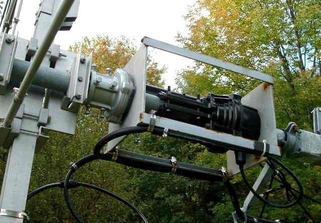 |
| Electrical Cable Support with Fuel Line Hose |
At the ends of the fuel line hose I use a small hose clamp to keep the protective sheath from coming off the cable, in the case of high wind or other disturbance. Three hose clamps affix the protected cables to the rotator cage. You can see those clamps on the arm which is on the bottom of the picture in this tilted over picture. The protection extends below the rotator cage, and even goes through the first stand-off arm loop. This can be seen at the bottom right corner of the picture. Since my cables are approximately 55 feet long they are easily held by their top end without problem. I do use high quality cable (LMR-400 UF coax and heavy-duty rotator control cable), and I suspect that helps. Even after years of use, I have detected no stretching or wear due to hanging.
Finally, here is a picture of the rotator cage on top of the tower, with the Sommer XP-506 on top. Please click on the picture for a larger view. An 80 Meter Inverted Vee is located under the beam.
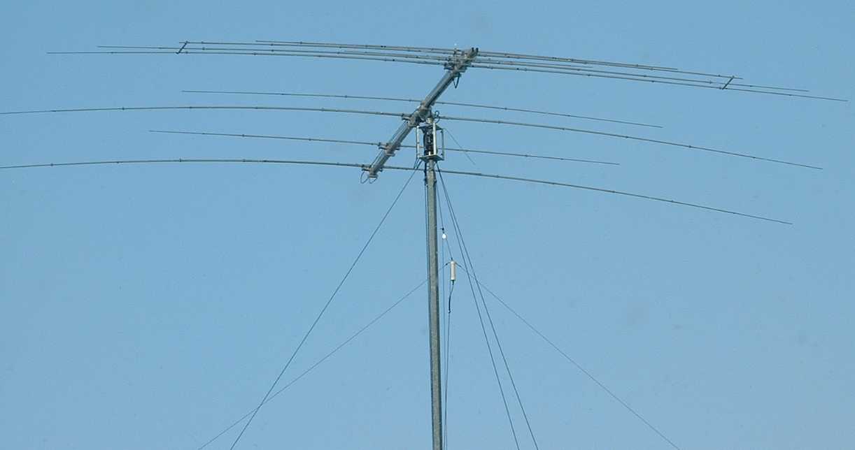 |
| Sommer XP-506 with 80 Meter Inverted Vee |
Back to my Experimentation Page