 |
| Two-Element NVIS Vertical Wire Yagi |
Greg Ordy
This page contains some supplemental information in support of my page that looks at adding a ground screen to an NVIS dipole. Adding a reflector wire creates a two-element parasitic Yagi. The Yagi is vertical, or pointed straight up, with the reflector directly under the driven element.
The question is: What is the impact of a single reflector wire, which is 5% longer than the driven element, and 0.15 wavelength under the same element? This page uses antenna modeling to generate the answers. The simulation program is EZNEC, which uses the NEC-2 engine. The reflector length and spacing are typical for NVIS designs.
I started with a standard dipole, made from #12 copper wire, resonant at 3.75 MHz. The ground model type is real/high accuracy, with medium characteristics (conductivity = 0.001 S/m, dielectric constant = 5). Here is a table of the model parameters.
| Simulation Parameters | |
| Parameter | Value |
|
Frequency |
3.75 MHz |
| Driven element length | 125 feet |
| Reflector element length | 131.25 feet |
| Wire diameter/type | #12 copper |
| Ground Model Type | real/high accuracy |
| Ground Characteristics | medium (0.001, 5) |
| Driven element/reflector spacing | 0.15 wavelength (39 feet) |
| Simulation heights (driven element) | 0.5, 0.375, 0.25, 0.152 wavelength = 131, 98, 66, and 40 feet high |
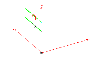
I decided to run simulations at 4 different heights about ground. In all cases, the reflector, if present, is 0.15 wavelength (39 feet) below the antenna. Here is a three dimensional view (from EZNEC) of the two elements.
|
|
| Two-Element NVIS Vertical Wire Yagi |
The 4 different heights mark the height of the driven element, which is the top wire. The heights, in wavelengths, are 0.5, 0.375, 0.25, and 0.152. The first three correspond to 1/2, 3/8, and 1/4 wavelength. That would seem to suggest that the final simulation height would be 0.125 or 1/8 wavelength. The problem with that height is that the reflector would be underground (since it is 0.15 wavelength below the driven element). So, the fourth height is selected so that the reflector wire is 1 foot off of the ground. The heights are representative of starting off with the reflector one foot off of the ground, and moving higher until the driven element is at 1/2 wavelength. Generally speaking, when a dipole is at 1/2 wavelength above the ground, the pattern and characteristics more and more tend to reach their free space values. In other words, going higher does not change the results to any great degree. With the reflector at the one foot level, some modeling guideline may be violated.
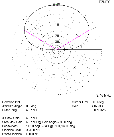
For each height, two simulations were run. One included the reflector wire, and the other didn't. The pattern of interest is the elevation pattern, since we are interested in the response at 90 degrees, or straight up. Captions are below patterns.
| NVIS Wire Yagi Simulation Results | |
| Without Reflector Wire (simple dipole) | With Reflector Wire |
 |
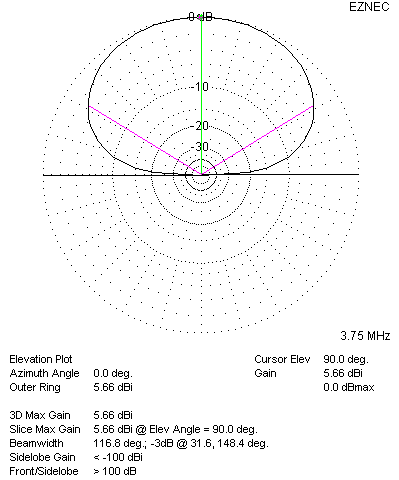 |
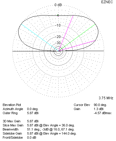
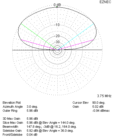
| Without Reflector, Dipole at 0.152 Wavelength (40') | With Reflector, Dipole at 0.152 Wavelength (40') |
 |
 |
| Without Reflector, Dipole at 0.25 Wavelength (66') | With Reflector, Dipole at 0.25 Wavelength (66') |
 |
 |
| Without Reflector, Dipole at 0.375 Wavelength (98') | With Reflector, Dipole at 0.375 Wavelength (98') |
 |
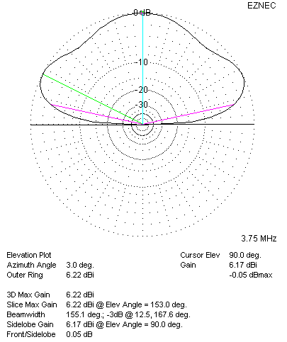 |
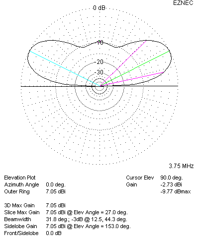
| Without Reflector, Dipole at 0.5 Wavelength (131') | With Reflector, Dipole at 0.5 Wavelength (131') |
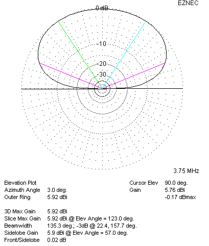
The azimuth patterns (not shown) show the typical dipole barbell shape, becoming more pronounced as the antenna is moved away from the ground. We are, however, looking broadside at the wide part of the barbell response.
To be clear about it, as you go down a column, antenna rises higher off of the ground. When you go from the left column to the right column, you add the reflector wire. Perhaps the most important number in each plot is the gain at the 90 degree (straight up) elevation angle. This is obtained by putting the EZNEC cursor at 90 degrees before capturing the window. The data is in the upper right portion of each plot numeric data area. For example, in the bottom left plot, the 90 degree elevation gain is -2.73 dBi. On the bottom right plot, it is 6.17 dBi.
The left column, Without Reflector, is simply taking a dipole and raising it higher and higher in the air. At the two lowest levels, 0.152 and 0.25 wavelength, the maximum response is effectively straight up. The gain is nearly constant, although it does drop from 4.87 to 4.82 dBi. At the 0.275 and then 0.5 wavelength heights, the pattern begins to flatten out, and the response at 90 degrees drops, first to 1.3 dBi, and then -2.73 dBi. So, if the goal of the dipole is to concentrate the power straight up, then lowering the dipole, at least to the 0.152 wavelength height, does indeed increase the gain. Raising the dipole lowers the gain at the at the 90 degree elevation angle. It should be noted that the overall maximum gain does climb with added height, going from 4.87 dBi to 7.05 dBi. At the same time, the angle of maximum response dips from 90 degrees to 27 degrees. These results support the conventional wisdom that a lower dipole is a better NVIS antenna, and that a higher dipole is a better DX antenna.
If we decide to continue to lower our dipole, the 90 degree gain will not continue to rise. In fact, it will soon start to fall, as the ground loss becomes dominant. For more information, consult the graph on this W8JI page.
In the right column, a parasitic reflector wire is added to the model. At the 0.152 wavelength top wire height, the gain does go up by 0.79 dB, so the Yagi effect is doing us some good. At such a low height, it's not clear to me if this is the Yagi effect, or, an increase in efficiency. On the NVIS: From the Backyard to Professional Installations page by W4RNL, his single reflector wire adds only 0.3 dB, but that is on a dipole at 0.2 wavelength high, which is slightly higher than my model.
My own conclusions from these models is that adding a reflector wire does improve the vertical gain, ranging from less than a dB at the 0.152 wavelength height, to nearly 9 dB at 0.5 wavelength. If you/re lucky enough to have an 80 meter dipole at a height of 131 feet off of the ground, and your ground type is medium, then adding a reflector wire dropped 39 feet down will improve your NVIS response by nearly 9 dB! Note that DX performance will be compromised. If I were lucky enough to have that setup, I think I would like to be able to switch the reflector in and out of the antenna system.
At heights below 0.25 wavelength (but above 0.152 wavelength), it may be difficult to measure or feel the improvement provided by the reflector. It is not clear from these simulations if a reflector makes an improvement, and to what degree, for dipoles lower than 0.152 wavelength.
Back to my 80 Meter Inverted Vee Page
Back to my Experimentation Page