2011 Update
Greg Ordy
I'm writing this update in June of 2011. I was able to use the vertical all last winter. That experience provided me with some performance data, as well a survival report over the first typical Ohio winter. The story of this vertical up to this point in time can be found on this page.
There is an update to the update, and it's at the very end of this page. It was added in August of 2011.
Being off of 160 meters for a few years, and not having a second comparison antenna, it's difficult to present rock solid performance data. I thought it worked very well. I worked all of the DXpeditions and DX that I chased. A number of stations came back with a you're very loud comment. Being a top loaded 90 foot tall vertical over 120 ground mounted radials and mid western soil should lead to good performance. The only surprise would be if the antenna showed poor performance. Of course using a 1500 watt amp and improving my transmission line does not hurt one little bit.
I really enjoyed the wider bandwidth of this antenna compared to the previous 70 foot center loaded vertical. With the shorter antenna, I was always watching the radio frequency, ready to select the small loading coil that provided a second SWR dip. With this antenna, I found that most all of my operating took place with one setting. From time to time I would move well above 1.850 MHz, and then the second SWR dip would come into play.
I've also slept a little better with the shorting relays. As described on the control box page, when power is removed from the antenna, the antenna is shorted to ground, and the radio sees a 50 Ohm dummy load. My hope is that this improves my protection against lightning damage.
The polycarbonate hinges survived winter without any apparent problems. Another idea that seems to be working out well is the use of the cut plastic conduit to protect the transmission line and control cable. I've been mowing the area around the antenna this year, and I just roll over the pipe with the tractor - no problems. I'm thinking of using this same idea on my vertical array. There, I have to coil up transmission lines to mow in the area, and it's a real waste of time to pick up the lines and then put them back.
The tower and raising fixture bases are described on another page. Since the bases were not encased in a big block of concrete, I expected some settling over winter, especially the first winter. The bases did indeed settle. The hinge pads are adjustable, and I have adjusted one on the raising fixture, and two on the main antenna. The maximum adjustment needed was about 3/8". I hope that after the first winter the ground will be stable going forward. I should check it once or twice a year to catch any shifting.
Those living in the USA will not soon forget the strong storms of spring, 2011. A number of early season tornados and storms pummeled the country. Where I live in Ohio, we rarely have tornados, but, the storms tend to pass over this region as they die out. We had several weeks of very strong spring storms and wind.
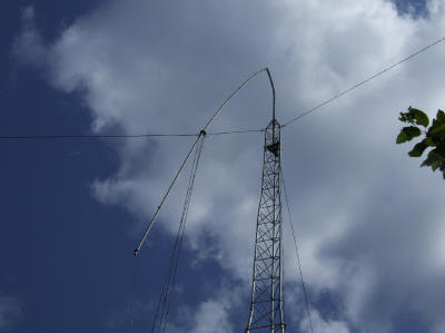
I called the original antenna the Wet Noodle 90, since it was 40 feet of aluminum tubing on top of a 50 foot aluminum tower. I kept an eye on the antenna all winter, and it stood tall through the normal snow and storms. It even stood tall through the springs storms - until the last few days. One morning, I looked out of the window, and found the wet noodle bent over.
 |
| Bent Wet Noodle |
In looking at the antenna system, this failure was entirely avoidable. The problem was that the elevated guy anchor point posts had shifted over winter, and tipped towards the antenna. This added some slack to the guy lines, and that provided enough wiggle room for the intense winds to work their magic. I suspect that if I would have straightened the posts, or the spring storms had not been so severe, there would not have been this problem.
I removed some dirt from the back side of each post, pushed them plumb, and then compacted the ground in front of the post. I need to keep on this until the ground settles around the posts, and they are permanently plumb.
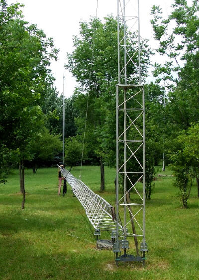
To avoid the wet noodle problem in the future, I decided to add 20 feet to the tower portion of the antenna and subtract 20 feet from the whip portion. I drove up to the Universal Tower factory near Detroit, and picked up two, 10 foot long, 14 inch face, sections. This gave me 70 feet of aluminum tower. I took the bent tubing, and salvaged all of the straight sections, and ended up with about 22 feet of tubing. I wanted a top whip that would no longer be a wet noodle. I continued to use the top loading wires.
 |
| Updated Antenna Before Raising |
This picture shows the rebuilt antenna while on the ground. All 90 feet went up without problem, and the raising fixture and winch did their job.
I cut up the bent whip into sections that were straight. Unfortunately, the damaged whip had a gentle bend it in, apart from the part that was folded over on itself. This meant that it was hard to find straight sections that were reusable. This was especially true at the bottom end of the whip. I also tried to increase the overlap to create more length with thicker walls. The end result was a rapid telescoping transition at the bottom of the whip. Here's a picture of the bottom of the updated whip.
 |
| Updated Whip |
I did spray the aluminum whip with a coating of gray primer paint. The idea is not protection but rather camouflage. An uneven coating of a flat gray or blue paint gets rid of sun glare, and helps make the whip invisible against the sky and clouds. I also usually coat the tubing with a conductive aluminum grease inside the joints. This hopefully preserves the conductivity across the joint. I don't really know if that's true, but it does make it much easier to take the tubing apart in the future.
After raising the new tower and whip, I checked the SWR. The resonant point of the antenna had dropped by approximately 100 KHz. This is due to the antenna being a few feet taller, and also the wider tower sections. This meant that I needed to retune the antenna. I was more than happy to do this since it means making the base loading coil smaller. I should end up with even more bandwidth with the slightly taller antenna.
For comparison, the original SWR dips are shown on this page. With the new configuration, the SWR dips for the two band selections moved down to:
 |
| SWR Dips Before Retuning |
The band edge is shown with the red line. I was collecting data at 5 KHz steps, so the absolute SWR low points are clipped. The base loading coil had 21 turns. The coil is shown on another page, but here's what it looked like right before I shortened it.
 |
| Base Loading Coil Before Retuning |
I connected a wire from the terminal on the right and touched turns until the SWR dip moved up into the band. When I had the final point, I cut the copper tubing and removed the end. It turns out that I needed to remove 4 turns. The modified coil looked like:
 |
| Base Loading Coil After Retuning |
The new DIP frequency was:
 |
| Measuring the SWR Dip After Retuning |
The low dip moved from about 1.730 MHz to 1.820 MHz. The SWR was rising just a bit at the new dip. Here's the reason. The radiation resistance of the antenna increased because of the increase in length. This means that the L network that matched the antenna back to 50 Ohms was no longer correct. Because the antenna resistance at resonance is increasing, the shunt matching coil in the L network also needs to increase. The L network has a smaller impedance step up, which means increased shunt reactance. I took off the cover on the control box and squeezed the turns on the matching inductor toroid. The improved SWR was:
 |
| Improving the SWR |
Another side effect of increased radiation resistance due to the longer antenna is a lower Q L network. This will improve the bandwidth.
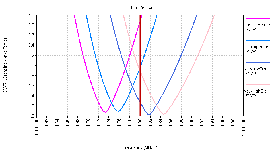
The final comparison between before and after retuning is:
 |
| Before and After SWR Dips |
By removing 4 turns from the loading inductor and then squeezing the matching inductor turns, I was able to move the two dips up into their places in the band, and also minimize the SWR.
All of the measurements were made at the base of the antenna.
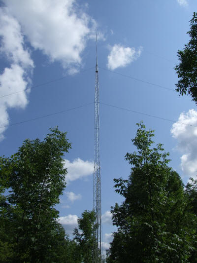
I'm hoping that the antenna is now ready for several years of service without further problems other than routine maintenance and checks. It is no longer a wet noodle. Here is a picture of the antenna after the repairs.
 |
| Repaired Antenna |
Since there were many weeks and months left before winter closes down the 2011 antenna work season, I apparently could not leave well enough alone. I felt I could improve a few aspects of the antenna, and hopefully insure there would be no problems over winter - when I want to use the antenna the most, and when working on it is usually impossible if there is a problem.
On another page, I described the elevated guy anchor points. Each rope was tied to a sturdy brass plated clip that attached to a screw eye. The idea here was to be able to attach and remove a guy line very quickly, and have the clip installed at the correct location on the line. It was also possible to add a safety cable that threaded through the closed eyes of the clips, making it impossible to quickly remove a guy. I viewed this as a small amount of anti-tamper protection. A photograph of this arrangement is:
 |
| Original Guy Anchor Point |
As mentioned on the first page, whenever you use rope, the subject of knots becomes important. Knots have a rich history, especially back in the day when sailing ships ruled the seas. When picking a knot for a given application, important points are the relative ease of untying the knot, and also the impact of the knot on the loading rating of the rope. Sadly, any time you bend a rope, you reduce the load rating at that point. Knots with more gentle bends tend to have less impact on the rating. So, picking the best knot for a given application can be tricky and involve trade offs between ease of tying and untying and the efficiency of the knot. The knots originally used were good quality, but were hard to adjust to a particular point on the rope. This meant that getting the rope tension optimally set was challenging and time consuming. In part, this contributed to the failure of the wet noodle, since there was too much slack in the top guy lines (even before the posts moved). Should the lines stretch, or the posts shift again, the location of the clips would be wrong, even if perfect at some point in time.
To allow for more precise and frequent adjustment of the guy rope tension, I decided to move to a design using horn cleats. I added two screw eyes to the original center eye to act as pass through points for the three guy ropes, and then each line attached to a horn cleat under the eye. I staggered the eyes vertically to visually associate each eye with a guy rope. The higher the guy on the antenna, the higher the matching eye on the post. I can no longer use the safety cable but that is a small price to pay to make it trivial to adjust the tension on each line with a very fine degree of resolution.
The updated guy anchor point looks like:
 |
| New Guy Anchor Point |
Another concern in the tension of the top guy lines (which exist for the top loading wires) was the diameter of the top whip tubing. When you increase the tension of a diagonal line, it can be expressed as a horizontal pull and a vertical downward pull. Usually, we want and seek the horizontal pull, since that's what stabilizes the structure. We accept the downward pull as unavoidable, and so long as the structure can handle it, it's not a problem. Since in my case the top guy lines attached around 90 feet in the air, and the base line length was 60 feet, the angle of the guy was quite steep (above 45 degrees). In fact, it's a triangle with a height of 90 and a base of 60, so the upward angle is 56.3 degrees. So, when I pull that top guy towards the ground, I'm applying more force down the tubing than force that stabilizes the tubing horizontally.
In the rebuilt top whip, I ended up feeling that the tubing I used was simply not thick enough to support the amount of downward force needed to properly tension the top guy lines. So, I got out my various tubing pieces that I've collected over the years, and rebuilt a new top whip. I used larger diameter tubing for more of the whip length. Generally speaking, the diameter increased from about 1.125" to 1.625". The bottom line is that I can use more tension on the top guy with the larger diameter whip. Since I was using bits and pieces of tubing in the junk box, the newest whip was about 2 feet shorter than the first rebuild.
I would like to reiterate that although I'm using an antenna tower as an antenna, this installation will NEVER be climbed by a human being. The decisions made about the guying and other design issues never considered a human climbing the tower. If a human is going to climb any tower, then all tower safety guidelines, rules, procedures, licensing, codes, and engineering regulations should be followed.
The last change I made was to extend the length of the three top loading wires from around 20 feet to around 25 feet. This change came about for two reasons. First, since the whip was now two feet shorter, the resonant frequency would go up if I made no other changes. This means that I would need a larger base loading coil to compensate, and that would be a painful change, especially after just cutting it down a few weeks earlier. So, I wanted to compensate for the slightly shorter top whip with longer top loading wires, not a larger base loading coil. After running some models of the antenna, I concluded that having longer top loading wires added a little bit of gain, improved the bandwidth, and allowed me to reduce the size of the base loading coil. These are all good things. The only problem would be if the wires were extended to the point where I moved the resonant frequency of the antenna (without any base loading coil) under the band. Now, I would need a capacitor with a very high value of capacitance (low value of reactance) at the base to give me some negative reactance to again achieve resonance in the band. Since large value high power capacitors have their own issues, I wanted to avoid them. So, the idea was to more than compensate for the 2 foot reduction in height, and allow me to further cut back the base loading coil, but not remove it completely.
The process of adjustment was similar to what was described earlier on this page. I selected a new coil tap point experimentally and also increased the matching coil inductance by squeezing the winding on the toroid in the control box. Both are necessary to move the SWR dip to a new frequency, and then make the dip as low as possible. I had to cut off three additional turns to get the antenna where I wanted it in the band.
After the adjustment, I ended up with the following pair of SWR curves for the two dips.
 |
| Before and After SWR Dips (August, 2011) |
I looked at the new and previous data in more detail, and the 2.0 SWR bandwidth did increase, from about 108 KHz to 114 KHz. Not much, but it is in agreement with the trend predicted by the model.
I'm hoping that I'm done fiddling with this antenna for a few years, and can simply use it. The one goal still not met is having a full size 1/4 wavelength 160 meter vertical without any loading at all - not at the top, and not at the bottom. To do that, I would need to add several more tower sections. My sense is that I would also want to make the raising fixture tower 10 feet taller if the antenna were to grow. The potential problem would become the ease of raising and lowering the second tower. At it's current 30 foot level, it's not a big deal for one person to walk it up and down. But, I do know that walking up a 50 foot aluminum tower is not easy, no matter what anybody says. I really don't know how hard it would be to walk up a 40 foot tower. I think it would be a moderate two person job, but no longer a one person task. Of course I could add a third tower to help raise a taller second tower to raise the main tower, but, let's not really think about that.
Back to the 2010 W8WWV Vertical Page
Back to my Experimentation Page