 |
 |
| Estimated Azimuth Direction | Over the Horizon Radar |
Greg Ordy
The 75 Meter DX Window is a 10 KHz wide frequency span which contains most of the world's SSB DX signals on that band. Since a SSB signal is at least 2 KHz wide, the window can be packed with frantic activity, depending upon propagation conditions. It's an important region of spectrum, a gentleman's agreement watering hole, where long distance communication can be found. I recently completed my Hex Array for 80 meters (well, 75 Meters, but I tend to mix the terms). This antenna gives me a directional signal for both transmission and reception, targeted for that window. This means that I can usually determine the direction of a signal with some moderate degree of accuracy.
As I started to use this antenna system at the end of 2003, I began to notice a noise source which often times sits right in the middle of the DX window. Its signal level is approximately S9 on my ICOM 756PRO radio, without preamp or attenuation. This means that the noise is often times louder than the DX signals. I finally decided to make an attempt to characterize the noise, and write up a web page describing it. Perhaps a reader can help identify it. I'm writing this description at the beginning of 2004.
Noise can take many different forms. As a problem, it is probably on the rise, since there are more and more electronic devices being used, and most have the ability to radiate RF energy, even if at a low level. Radio receivers are designed to pick up weak signals, so it takes very little energy to compete with an actual desired radio signal.
Noise can be very local. It can be generated by a light dimmer in the dining room, or a computer sitting next to the radio. It can come from a loose wire in a fuse box, or a bad insulator on a telephone pole. Noise can develop over time. Metal to metal mechanical connections can corrode over weeks, months, or years, creating a diode-like junction which can be involved with noise generation. These are but a few of probably hundreds of possible noise sources.
Noise can also be more global. From time to time commercial broadcasting stations suffer defects that cause them to begin radiating undesired energy, usually at harmonically related frequencies. The planet is more and more littered with remote unattended data gathering stations, such as for collecting weather data, or ocean information. When these fail, even partially, they can radiate signals on undesired frequencies. Beyond these commercial accidents, there are deliberate noise sources which can show up in the middle of amateur radio bands. Most nations have spy (intelligence) and military operations that like to operate in very secret and mysterious ways. The signals they generate range from endless streams of spoken numbers to radar and early warning detection systems.
When you are faced with noise that compromises operation, it's best to come up with a methodical approach that attempts to locate the source, usually hoping that it is local so that there is a chance that it can be fixed or reduced. The ARRL publishes The ARRL RFI Book, which is a very good resource for tackling noise, as well as interference caused by amateur operation.
In my case, my best guess is that the noise I am hearing is not local. That guess comes from considering the usual sources of local noise, and how they would be picked up by my station. My set of symptoms does not seem to match locally generated noise. I certainly could be wrong, however.
My first question was, where was the noise coming from? I could only detect the noise when my array was pointed in the 30 degree or 90 degree directions. The array has a computed 3 dB beamwidth of 70 degrees. I find that when a signal is coming from a source which tends to land between two of my fixed directions I'm more able to determine it's direction. If the signal strength was the same on two adjacent directions, then that's a strong indication that it is coming along a line half way between the two directions. As the signal moves off of that center line, one direction will tend to have more signal, and the other less. The relationship between these two strengths should be able to be mapped into a direction offset, but I've never tried to be that precise.
In this case, the signal strength was slightly stronger on the 90 degree direction. My azimuth estimate is 65 degrees. The center line is 60 degrees, so the shift to 65 degrees reflects the small signal strength increase on the 90 degree direction.
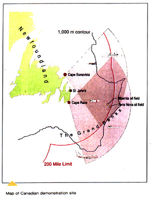
My array is controlled with a program called HexER. I used a screen capture program to capture the window when it was pointed in the 90 degree direction. I then added a wider red line on the map with a bearing of 65 degrees. That map is shown in the left picture below.
|
|
|
| Estimated Azimuth Direction | Over the Horizon Radar |
Now I had remembered reading about radar systems that used shortwave frequencies as opposed to much higher frequencies so that the system could see over the horizon (OTH). I started to search the Internet using a number of search terms. I can across a page from Radio Netherlands. Although this page seemed to be a few years old, it included a map which really caught my attention. I have copied it to the right picture above. I would have preferred to link to the picture, but I felt it necessary to show my map next to theirs.
My wide red line cuts exactly across the heart of the radar field shown in their diagram. Coincidence? I don't know, but the eastern tips of both the United States and Canada are largely located along my line, and if either country wanted to get the best penetration into the ocean, it would make some sense that they would locate transmitters at their eastern tips.
I only receive the signal on my 30 and 90 degree directions on the array. On the other four directions I cannot detect it. It does not show up on my Inverted Vee. The typical signal strength on my receiver, without preamp or attenuator, is S7 to S9.
I cannot find a pattern to when the noise will be present, it certainly is not constant. During the local daylight hours here, it tends to be mainly off. It will come on for few seconds, and has a duty cycle of perhaps 20 percent. In the evening hours, they are times when it is constantly on.
What really got my curiosity going was the shape of the noise signal on my radio spectrum scope (ICOM 756PRO). It is a signal with a definite shape that spans several KHz. The signal covers approximately 8 KHz, centered near 3.795 MHz. I used a typical web cam to capture some video of the signal on the spectrum scope. Here is a captured frame from the video. It was taken on Sunday, January 11, 2003, at 19:44 Z (2:44 PM, local time). The scope was set to 5 KHz per horizontal division.
 |
| Spectrum Capture of Noise |
I drew the yellow line onto the display with the Paint program. I was trying to capture the overall shape of the noise signal. The shape is quite apparent if you observe it as moving video. It appears to consist of three spikes of energy, with small gaps between them. The spikes seem to move down (right to left) in frequency, with the strongest signal on the middle spike. It has a certain undulation. The overall shape follows a bell-shaped or Gaussian distribution. The video is available as a low resolution file (72 KB) and a higher resolution file (480 KB). You will probably need a recent version of Windows Media Player to view these asf files.
It sounds like a buzz, not a carrier or some typical modulation.
I have recorded a few seconds of the noise, which I have converted to an mp3 format file. It can be played by clicking this link. The file is almost 400 kilobytes long, and contains around 30 seconds of audio.
If you have any ideas about what this noise could be, please contact me. I doubt if I can do anything about it, but I would sure like to know what it is.
On February 3, 2004, I happened to notice that a signal with the same signature appeared on 3.783 MHz, which is about 12 KHz below the signal I reported at the start of this page. The time was approximately 20:00 Z. The signal was arriving at an azimuth angle of 350 degrees with respect to my location. At no time did I ever hear the signal on 3.783 MHz on at the same time as the 3.795 MHz signal. The February 3, 2004, signal had the same unmistakable curve and undulation.
On February 7, 2004, I found the signal on 3.768. It was 18:00 Z, which is early afternoon here. The band was so dead that I could hear the signal even on my Inverted Vee. It was much stronger on the array, and coming in at an azimuth angle of 350 degrees.
Ok, Ok, Ok, skip the idea of this being a distant signal. It appears to be local.
On Tuesday, February 14, 2004, I received some inspiration from Pete, N4ZR. He pointed out that even if I could not immediately hear the noise with a portable radio, if the signal was local, I should be able to get close enough to it that it could be heard. Since I believed I had a bearing, one good way to determine if the signal was local was to drive in that direction and see what happens. Time to get out of my chair and do some driving around.
On another web page I described a small receiving loop I used on 80 meters. I had several in the attic. I grabbed a length of plastic pipe and cut it so that it just came out of the moonroof on my minivan. The loop base fit into the pipe. I can rotate the loop with the Armstrong method. I attached the coax to my ICOM 706MKIIG which happened to be in the minivan. For about 5 minutes of effort, I had an 80 meter mobile directional monitoring station. Makes me wonder why it took so long. Here's a picture of what I was about to drive around in. Please click on the picture for a larger view.
 |
| 80 Meter Mobile RDF |
The loop has signal lobes off of the end, and sharp broadside nulls, especially at a low angle. The nulls are usually used for direction finding. With bidirectional null you have two directions, not one. But, by determining multiple bearings you can draw lines which should intersect.
I saerched for my copy of the township zoning regulations. I remembered that there was a township map in there with all of the parcels outlined. I though that this would be the most accurate local map I could easy obtain. Having the property lines available was also nice, in case some location popped out as being suspect. I also grabbed my compass, which I first purchased to align my rotator.
It was early afternoon, and I made a quick check of the band. While the signal was not in the DX Window, it did appear to be at 3.831 MHz. Another new frequency. The key was the signature on the spectrum scope. It's hard to miss. The signal was also coming in on the previous 65 degree bearing. It seemed to be time to try out the new mobile detector.
I was pleased to find that I could detect the signal in my driveway. I didn't have a spectrum scope on the 706MKIIG, but I knew the frequency, and I could hear the buzz. I rotated the loop to find a null. I aligned the compass with north, and measured a bearing of 68 degrees. This agreed quite closely with my earlier estimate of 65 degrees. I live in an area of several main roads, and a lot of cul-de-sac streets filling in the large rectangles. The cul-de-sacs have very little traffic, so stopping to make a measurement is not a problem, except for looking very strange. Sort of like a new version of Hogan's Heroes, where the radio direction truck is driving through the countryside, trying to detect those nasty spies.
As I was leaving, I knew I wanted to drive in the direction of the signal. If the signal source were far off, then it's signal strength should remain somewhat constant (just QSB and terrain issues), and all of the bearings should remain the same. If the transmitter was 1000 miles away, then driving a few miles in any direction is not going to make a measurable difference.
The results were quite illuminating. Here's what my map looked like:
 |
All of the lots are at least 5 acres. I live in the yellow lot. For scale, my frontage on the street is about 650 feet. The red line though my lot is the 68 degree bearing taken in my driveway. Other lines were made by stopping at low traffic points on side streets. The lines do seem to converge on the blue lot. And, indeed, there is a house there, and it is located at the rear of the lot, where the lines seem to intersect.
At this point, I'm going to acquit the governments of Canada and the United States. They do a lot of bad things, but apparently messing with the DX Window is not now on the list. I need to remake these measurements, and probably try to keep a time log of the noise, and then contemplate a conversation.
Back to my Experimentation Page