|
| 1/8" Stereo Electret Condenser Microphone to ICOM 8-pin Microphone Connector |
Greg Ordy
I recently had the opportunity to explore the topic of interfacing brand-X microphones to ICOM radios, first the IC-756 standard, then the IC-756PRO. Here's what I discovered.
The goal is to have a microphone drive the radio with an appropriate signal level. What really matters is that the two work as a pair. We want a matched system. Many ICOM radios have a reputation for requiring a stronger microphone signal than other radios. In fact, some third party microphone vendors sell a pre-amp specifically designed for ICOM. This issue became real for me when I replaced my Yaesu FT-920 with the ICOM IC-756.
When the Yaesu FT-920 was my primary HF radio, I used an Audio Technica (ATH-COM2) microphone/headphone (headset) combo. I really liked the headset because it had high quality earphones, a good sounding microphone, and it was lightweight. It was also moderately priced. When the ICOM IC-756 arrived, I was hoping to simply use the same headset with the new radio.
I quickly learned that the Audio Technica microphone did not drive the ICOM IC-756 nearly as well as the supplied HM-36 microphone. With the HM-36 microphone, the radio was fully driven with the microphone gain control at around 10:00 o'clock. The Audio Technica microphone could not generate an acceptable signal level even with the microphone gain near maximum. Something was very different.
In the end, it's this simple. The output signal that a microphone produces will be related to the microphone (element) technology. Two different classes of microphone are popular in this application area. One is the dynamic element, and the other is the electret condenser element. A dynamic element generates a signal which is approximately -55 dBV. An electret condenser element signal is approximately -35 dBV. That difference, 20 dB, is a 100X difference. Please note that these signal levels do vary quite a bit from microphone to microphone.
As best as I can tell, ICOM has designed their radios to expect the higher electret condenser level. I think that this is a reasonable assumption because their accessory microphones, the SM-8 and SM-20 are described as having electret condenser elements. In RF or electrically noisy environments, the stronger microphone level may improve RF feedback immunity through the microphone. In other words, the microphone and its cable may act as less of an (undesirable) antenna.
In checking my Audio Technica headset, I found that it was a dynamic element. The lack of signal drive finally made sense, I was using a microphone of the wrong type. I was 20 dB short of a load, so to speak.
Ok, so all I needed was a headset with an electret condenser microphone element.
So where does one get electret condenser microphones? Turns out that they have become the standard microphone element to drive the generic computer sound blaster card. Was this always true? As best as I can tell, the answer is no. In fact, over the last few years, the generic sound blaster card has changed from accepting a dynamic microphone element to an electret condenser element. Apart from any business reasons, my assumption is that this was done to improve the signal to noise ratio of the microphone system. A digital computer can be an electrically noisy box. By putting 20 dB more gain in the microphone, and removing 20 dB from the audio board, the microphone and its cable becomes less of an unwanted antenna (since there is less amplification in the box). I also suspect that electret condenser elements are simply less expensive to make and sell than dynamic elements. The enormous quantities sold to the computer market also drive down the cost.
So, if you want an electret condenser microphone, head to your computer store. Check the packages, but odds are that most of the products are electret condenser. These microphones tend to be rather inexpensive. I purchased both a Plantronics headset and a Radio Shack headset for less than half of the cost of an ICOM SM-8 microphone. I get great audio reports with either.
If you are really out to cut cost, Radio Shack and other sources sell the electret condenser element by itself. Usually, these elements cost no more than a few dollars. This might be attractive if you want to replace an element and keep the microphone shell.
Finally, I did notice that the most recent sound blaster card I purchased came with a switchable 20 dB pre-amp in the microphone input chain. When I go to the software mixer control panel, I have a check-box that will add or remove 20 dB of gain. It's my guess that this is exactly designed to let the card accept either element type. My cards that are a few years old expect a dynamic element level. I suspect that in a few years they will all expect the electret condenser level.
All that's left is to wire it up. Turns out that also became a lesson. The problem stems from the fact that electret condenser elements must be powered. Usually any voltage between 1 and 12 volts will work. The current draw is very low. While some microphones will use their own battery, most expect to get power from the radio (or whatever it's plugged into).
If you examine the male plug at the end of most electret condenser microphones, you will find a 1/8 inch (3.5 mm) stereo plug. It's very easy to jump to the conclusion that the three terminals must be ground, signal, and power, most likely on the sleeve, tip, and ring, respectively. For the several microphones I checked, all coming from computer applications, the plug was stereo, but the cable was mono. The tip and ring terminals are connected together within the molded plastic plug. By the way, the plugs on computer microphones tend to be red in color. This matches the color on the jack, making it easier to determine where the plug belongs.
This implies that the signal wire and the power wire are the same wire. This will work, so long as you use a blocking capacitor to keep the DC voltage off of the audio input, and a resistor to allow a voltage drop as the signal level changes.
Let's get very specific. On my ICOM radios, pin 1 of the front panel 8-pin microphone connector is the audio input. I connected a 10 uF capacitor to this pin. Pin 2 of the connector is the element power, which is +8 VDC. I connected a 2.2K ohm resistor to that pin. The free end of the capacitor, which is also the (-) end if the capacitor has polarity, is connected to the tip terminal of a 1/8 inch (3.5 mm) female jack. The free end of the resistor is connected to the ring terminal of the 1/8 inch jack. the third connection is ground, pin 7 on the connector. Ground is wired to the sleeve terminal of the jack. Since I use VOX, and my headset does not have a PTT (push to talk) switch, I do not need to wire up the PTT pin. Your application may differ.
While at first this seemed confusing, it really does make (clever) sense. This circuit allows the microphone cable to be mono, as opposed to the more costly stereo. It is also possible to plug a mono dynamic element into the same circuit. The worst that happens is that the full power supply voltage is placed across the resistor. The current drain would be approximately 3.6 mA, which is very low.
|
| 1/8" Stereo Electret Condenser Microphone to ICOM 8-pin Microphone Connector |
A quick comment about the capacitor (C1) polarity. A large value capacitor is used so that it presents a very low reactance at audio frequencies, and does not begin to act as a tone control. Most of the capacitors in our junk boxes, above 1 uF, are electrolytic, meaning that they have an indicated polarity. In operation, it is desirable to connect the + or positive side of the capacitor to the side that has the more positive DC potential. If you get the polarity wrong, the leakage of the capacitor can increase, potentially to the point of passing DC through the capacitor, which is exactly what we are trying to block. Furthermore, an electrolytic capacitor needs a DC voltage across it to properly interact with the chemical paste which is part of the capacitor construction. On many ICOM radios (see the comments at the end of this page), pin 1 already has +8 VDC, and that will make it the more positive terminal, especially in the case when the microphone element has separate power and signal lines. The schematic just shown is correct, on the assumption that pin 1 already has a positive voltage and that the tip terminal is closer to zero volts. In your circuit, you should measure the DC voltage on each side of the capacitor, and connect the positive lead to the positive side. If both sides have the same positive voltage, that is a good suggestion that the capacitor is not needed, since there is not a DC potential difference to block. If you look at a range of ICOM microphone schematics and other microphone sources, you will see the polarity specified in both directions. The right answer is that if there is a potential difference, match the capacitor polarity to the difference, or, don't use the capacitor since DC blocking is not needed. Thanks to Julius, W2IHY, for bringing up this issue to my attention. By the way, the W2IHY audio equalizers are popular external devices for tailoring your transmit audio.
NOTE: After considering more sources, the use of a electrolytic capacitor in this application really does not make sense. A much better choice would be a 1 uF non-polarized tantalum capacitor.
I needed a case to hold the capacitor and the resistor. I wanted something small. I also wanted it to be a metal case, to get the best possible shielding. My solution is shown in the following picture.
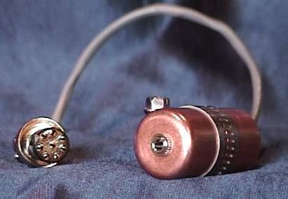
The passive components are placed within a small capsule created by placing two 3/4 inch copper pipe end caps back to back. The two caps are held together with a hose clamp. One end cap is drilled to hold a 1/8 inch (3.5 mm) stereo jack, and the other end has a rubber grommet that surrounds the shielded microphone cable as it exits the capsule. There is plenty of room inside the capsule for the capacitor and the resistor. I use about 6 inches of two-wire shielded cable to connect the capsule to the connector.
By the way, Radio Shack sells the 8-pin microphone connector that is used by many ICOM radios, certainly the IC-756 standard and the PRO.
With this adapter cable I can easily connect any of the common electret condenser microphones to the radio. One could choose to wire the microphone cable directly to the ICOM connector, so long as the capacitor and resistor are included. Since every microphone I had presented a 1/8 inch (3.5 mm) stereo plug, and I didn't want to cut off all of their ends, I built the capsule so that they all could be simply plugged in.
When I decided to get an IC-756PRO, I assumed that it would have the same input characteristics. Apparently ICOM has been influenced by this issue since I found that I could drive the PRO with a dynamic element. From what I can tell, they have added additional gain to the microphone input circuit (as compared to the 756 standard). An electret condenser element in a headset situation, with my voice characteristics, will drive the radio fully with the gain control at slightly less than 9:00 o'clock. My old Audio Technica dynamic element will drive the PRO with the gain control at noon.
Several people have written me concerning this page, and pointed out that my solution is probably overkill. That is, the front panel microphone jack audio input line on many ICOM radios already has a positive DC voltage on it, which can directly power an electret condenser element. In this case, the external components I have specified on this page are redundant, and not necessary. Indeed, I went through the painful process of following my 756PRO schematic diagram, and did find that the true audio input was fed through a DC blocking capacitor, and that the line was tied to 8 volts DC through a dropping resistor.
If your electret condenser microphone requires separate audio and power wires, then you have no choice but to build something similar to what I have described here. In the case of the sort of microphone (computer) I have described on this page, even if the microphone plug is stereo, don't assume that means separate signal and power wires. I found that every microphone I tested had a stereo plug which was immediately reduced to two wires (tip and ring were wired together).
My suggestion is to begin by testing the audio input pin of the ICOM radio for the presence of approximately 8 volts of DC. If you find the voltage there, you can directly connect your electret microphone without any extra components. The single wire holds both the power and audio signals. If you do not find the DC voltage on the audio input pin, then my circuit will do the job.
For me, my interfaces tend to also be about substituting different connectors. With my 756PRO, I wanted to be able to plug in a garden-variety computer headset with a 1/8" stereo plug. For my mobile/portable 706MKIIG, I wanted to plug in a similar headset, but this time to the modular connector on the 706MKIIG. Those connector interfaces provide a convenient place to add the dropping resistor and blocking capacitor. So, I'll probably add them just in case I ever have an electret condenser microphone that truly requires a three-wire interface.
The simplest interface which allows computer microphones and headsets is shown in the following picture. Please click on the picture for a larger view.
 |
| Simplified ICOM Microphone/Headset Interface |
I took a female 1/8" stereo jack, in a molded plastic shell, and connected the tip and ring wires to pin 1 (audio in) of the ICOM microphone connector. The sleeve wire is connected to pin 7 (ground) of the ICOM connector. Plug in the microphone (usually the red plug), and you are in business. The headphone plug can be put through a 1/8" to 1/4" stereo adapter to change sizes for the ICOM headphone jack.
Back to my Experimentation Page