|
706 Mount (unfinished) |
Greg Ordy
This page describes a very simple and inexpensive mobile mount for an ICOM 706MKIIG radio. This design would also work with other models of small and relatively lightweight radios. I built the mount for my Nissan Quest minivan. While the identical design probably won't work in most vehicles, I hope that there are some ideas and concepts presented here that can be adapted for other situations.
I wanted to use my 706MKIIG for more than mobile operation. It is also my portable and backup radio. This means that I didn't want to permanently mount it in my vehicle. I needed a mount that would allow the radio be added to or removed from the minivan in a matter of seconds. I use a Hamstick style antenna, which is attached to the center of the roof with a triple magnetic mount. The thin coax (RG-58) is routed through the mid driver's side window. There is enough flexibility in the window gasket to allow the coax to enter the passenger compartment without compromising the window lock. Other than drilling a single hole in the firewall for the +12VDC power cable, I have not modified my vehicle in any way.
My Nissan Quest minivan, like most minivans, is very roomy. I previously operated mobile with an old Kenwood TS-440, which is a much larger radio. It fit between the front seats and the dashboard with room to spare. The problem was not finding room to mount the radio, but rather a scheme that firmly anchored the radio at the desired position while not modifying the vehicle. Although the 706MKIIG features a detachable front panel, I was hoping that I would not need to use that capability. If I could keep the radio together, the installation and removal procedure would, no doubt, be simpler. Again, this is not a permanent mount. The radio spends far more time out of the vehicle than in it.
The mount described on this page cost less than $8.00 (USD) in parts. It took about 2 hours to construct. Please note that the mount assumes that you have the MB-62 radio bracket. This is an extra cost (approximately $25 (USD)) accessory and is not included in my $8.00 (USD) total.
A mobile mount should hold the radio firmly at the desired location. Finding the right location is usually the easy part. The radio should be located where it can be easily and safely viewed and adjusted. It is also required that all necessary cables can connect to the radio. In my case, this included the power cable and the antenna coax. In some installations there might be an additional ground wire. In some situations, the radio location may be influenced by a desire to keep the radio more nearly out of sight, to reduce the risk of theft. The location of the radio might be influenced by thermal considerations. Placing the radio up against the heater vent, or in a small enclosed space under a seat, might not be very good for the radio. Above all else, the location of the radio should not interfere with the safe operation of the vehicle.
In my case, I like the radio to be located between the driver and the passenger seat. My right arm, when resting on the seat arm rest, should be able to comfortably adjust the radio. The radio is tilted up at a very sharp angle, approximately 60 degrees from horizontal. The radio must be far enough back from the dashboard so that I can still operate the controls on the dashboard, but not so far back that it restricts the use of the all important cup holders.
One of the things that I have learned is that the radio must be firmly mounted. Rapid starts, rapid stops, and sharp turns, create substantial forces. The radio must act as if it is part of the car. It cannot sway or rock. In general, stability can be improved by widening the base of an object. Consider a camera tripod. My experience, however, has been that in the mobile environment it is impossible to gain sufficient stability without finding a way to anchor the radio directly to the vehicle. The trick in this case was to do that without drilling holes.
If you're willing to drill holes in your car, finding anchor points is very easy - you can create your own. In this case, I did not want to permanently alter the minivan. In my particular vehicle, the front seats have several screw holes on the inner sides facing the center of the minivan. The screws are located at the bottom of a molded plastic hole. Two of the holes are located right at the carpet level. I can use these two holes as my anchor points. If a straight rod can be trapped between the opposing holes, it will be firmly anchored to the vehicle, and located right at the level of the carpet. The rod will span the space between the seats, near the front of the seats. This region is almost directly under the desired radio location.
In other vehicles, it might be possible to temporarily loosen a seat mounting screw and attach a support to that point. Do not compromise the strength of the seat. Perhaps more than one support point will be needed. Many cars now have large and heavy custom floor mats that are pinned in place (so that they don't shift around). It might be possible to place a piece of wide and long aluminum flat stock under both front mats. A mount could be attached in the middle of the cabin, where the stock is exposed between the mats. Finding suitable anchor points may very well require out of the box thinking.
Once you have determined the anchor points, and the desired radio location, the remaining challenge is to connect the radio to the support points. Almost any material can be used. Metal, wood, and plastic are all possible materials. For the 706 I used wood, my TS-440 mount was built out of aluminum.
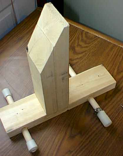
The following picture shows the mount.
|
706 Mount (unfinished) |
The bottom horizontal support is a 15" long piece of 2X4 lumber. The left end is towards the front of the car. The outrigger arms are made of 3/4" hardwood dowel. The left (or front) dowel provides lateral stability. The ends are covered with 3/4" rubber caps. The right (or rear) dowel is sized to span the space between the anchor points. The ends of the rear dowel hold a hose clamp and a nylon coupler designed for plastic water pipe. The nylon coupler smoothly slides over the dowel. When the mount is placed in the operating position, the couplers are slid away from the center, and then inserted into the holes on the side of the seats. The hose clamps are pushed up next to them and tightened with a penny. The rear dowel is now pinned to the seats, and the entire mount is held firmly against the floor.
The riser is made of two sections of 2X4 lumber. The overall length is approximately 14". The pieces are glued together, and they are inserted into a dado (channel) in the horizontal support. The dado is 3/4" deep. Two long wood screws come up from the bottom of the horizontal support and into the vertical riser. Glue is also used to join the riser to the horizontal support.
The top of the riser is cut at a 60 degree angle with respect to horizontal. This is the angle that creates the best viewing angle for me. Your angle may vary.
Several inches of wood extend to the right of the rear dowel. It might appear that the horizontal support could stop immediately to the right of the rear dowel. There were two reasons that I did not do that. First, and foremost, the wood to the right of the rear dowel is needed to make sure that the entire mount does not rotate towards the rear of the vehicle in the case of rapid acceleration. Second, it also provides a convenient place for adding a small speaker. I found the the speaker in the 706 had too much treble response. I had a computer speaker lying around, and it seemed to provide good audio when connected to the 706. That speaker is glued to the horizontal support immediately behind the vertical riser.
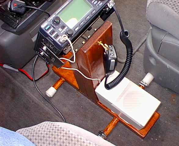
I completed the mount with a maple-colored stain/polyurethane combination finish. Here is a picture of the finished mount, installed in the minivan.
|
Finished 706 Mount in the Minivan |
You can see the right nylon coupler extending into the hole in the side of the passenger seat. This is an anchor point. A hose clamp keeps the coupler in place. The power cable goes towards the firewall, and the antenna coax goes under the driver's seat towards the center window. I added a kitchen cup hook to the vertical riser which acts as a microphone holder. The radio bracket, the MB-62, is attached to the angled portion of the riser with wood screws. The 4 screw heads are visible in the picture.
The computer speaker is glued to the horizontal support. It points nearly straight up, which is directly towards the driver's and passenger's ears. The speaker wire terminates in a plug which goes into the front panel of the radio.
The flip down cassette tape compartment in front of the mount still opens fully, and the cup holder on the passenger seat flips down fully and functions normally.
Back to my Experimentation Page