 |
| CW Envelope Examples |
Greg Ordy
Although CW is claimed to be a dying mode, the recent discussion of key clicks has been quite lively. A key click is the undesirable result of a CW envelope with short rise or fall times, and/or sharp transitions. Substantial transmitter energy may be delivered over several KHz (kiloHertz), as opposed to several hundred Hz (Hertz). This defect is not the same as the classic chirp, which is a frequency shift within a CW note (dit or dah).
During 2002, the CW transmit performance of the classic Yaesu 1000D and 1000MP transceivers, with respect to clicks, have been under increasing scrutiny. These clearly are not the only radios with CW click issues. These radios are simply very popular with the DXing and contesting communities. Clicks are very disruptive to weak-signal DX work, as well as crowded contest bands. In the extreme, a click might take a transmitter out of compliance with applicable rules and regulations.
There are some modifications which can be made to these radios which reduce the strength of the CW clicks. Tom, W8JI, has been out in front of this whole problem, and his web pages include modification instructions for these radios, as well as general information on key clicks. INRAD, the popular filter supplier, sells a key click mod for these radios. INRAD has published a web page with information on its mod, as well as a number of spectrum plots for several radios. The 1000MP mailing list reflector on www.qth.net has actively discussed this topic.
What does this have to do with me, since I currently operate an ICOM 756PRO radio?
There are issues for the receiver, and the transmitter.
When I started to use the 756PRO, I commented on another web page that the receiver had a different sound than the analog radios I had been using up to that point in time. This was especially true when operating CW. Other sources suggested that the nature of the PRO's DSP IF made it possible to more clearly hear defects in the transmitter - defects that other receivers might not be able detect. Over the last two years, due to more experience with the receiver, I have come to the conclusion that much of what I have been hearing is indeed key clicks. One of the nice features of the PRO (and PRO II) is that you can set the receiver bandwidth as narrow as 50 Hz. It's very illuminating to use this very narrow setting and tune across a signal on an otherwise empty region of a band (such as 160 meters). Of course overly sharp receiver filters can result in ringing, which can be confused with issues over at the transmitter. One must also be careful to avoid overloading the receiver, which would distort the signal analysis.
On the transmit side, the question becomes: does the 756PRO generate key clicks? When I was first setting up the radio, I remember passing by a menu item that selected the CW Rise Time. I never played with that control, and I was interested to see what it did, and what impact it would make on the transmitted signal.
The remainder of this web page looks at the effect of the CW Rise Time control located in the radio menu system. That control is the only adjustment that the user can make (without modifying the radio) which will alter the CW signal on transmit. By the way, I assume that the 756PRO II has the same capability.
At the end of January, 2003, the information on W8JI's web page made it to an article on www.eHam.net. As is the policy of eHam, the information is followed by a large number of interesting comments.
It appears as if the difference between very serious clicks and very minor clicks amounts to no more than a few milliseconds. Conceptually, a CW signal seems as if it should be a square wave, where the signal is either fully on, or fully off, with instantaneous changes between the two extremes. Practically, this is unachievable, as well as undesirable. The steep rising or falling transitions cause the key clicks. A square wave CW signal would have a significant key click problem. Both the rising and falling transitions are important.
I should also mention that it is insufficient to simply consider rise and fall times. Clicks will be reduced when all transition edges are rounded, not sharp. The only waveform which has no harmonic content is the pure sine wave. Any deviation from that shape will represent the addition of energy at higher frequencies (wider sidebands). The ideal CW signal would use a portion of a sine wave curve to transition between the on and off states. Some radios exhibit a rounded transition. More recent radios seem to exhibit a linear ramp between on and off states. Both of these approaches can still generate clicks, even with long rise and fall times. Any edges (or knees) between envelope sections, no matter how small, can cause clicks.
Envelope timing is also constrained by the keying rate. As the keying speed increases, the duration of a dit (the smallest Morse Code element) drops. Obviously the envelope must be able to fully rise and fall within the dit. This issues does not become significant until the keying speed reaches approximately 40 WPM (words per minute). If the transitions are too long, the signal is often described as mushy or soft, as opposed to crisp or sharp.
The following picture shows some CW envelope examples. I am hardly a CW expert. These envelopes are simply representative of classes of signals that I have seen over the years in books and magazines.
|
|
| CW Envelope Examples |
I have only shown the top half of the envelope. An actual envelope would usually be symmetric above and below the X axis.
Envelope A is a square wave. While it would appear to be the ideal envelope for what amounts to an on/off signal, it is rich in clicks due to the vertical transitions, and the shape edges shown in the red circles. As mentioned earlier, both the rising and falling sides of the envelope have the potential to generate clicks.
Envelope B is my poor attempt to draw an envelope where the transitions follow the shape of a sine wave. There are no sharp edges or vertical sections. There are appropriate names for this minimal click shape. These have been describe as being a raised-cosine, or Gaussian.
Envelope C is often times the signature of a directly keyed transmitter. By directly keyed I mean that the transmitter keying input is directly connected to the oscillator and/or amplifier. It was possible then to use simple RC networks to impress an exponential transition onto the carrier. This once seemed to be the common shape of many vacuum tube transmitters.
Envelope D has been appearing more and more with the modern semiconductor transmitter. It appears to be a deliberate attempt to reduce clicks by introducing a trapezoid shape onto the carrier. While the transition is no longer vertical, there can still be problems due to the sharpness of the top and bottom corners. The red lines indicate the duration of the rise time. The ARRL measures this time between the 10% and 90% signal levels. I simply measured the time between the 0% and 100% levels. I suspect that part of the reason that common envelopes have moved from C to D over the years is that the transmitter has become surrounded by microprocessors and other digital circuitry. Most all modern radios have internal CW keyers. This means that the actual key input wires are nowhere near the oscillator or amplifier stages. Our CW envelope is at the mercy of the radio designer.
As the pictures in the next section will show, the ICOM 756PRO exhibits a D envelope. The transition time can be set via the front panel menu. Four different values are possible, 2, 4, 6, and 8 milliseconds. The factory default is 4 ms.
According to the W8JI page, the ARRL recommends a 5 ms transition. He uses 6 to 7 ms. Many unmodified radios are in the 1 to 3 ms range. As his spectrum analyzer pictures show, this difference of a few milliseconds can make a 30 dB difference in the key click level.
While it is useful to examine the actual keying envelope, the more useful measurement is the resulting signal spectrum. The spectrum analyzer is an excellent tool for evaluating CW envelopes since it clearly indicates the resultant signal levels of the spectrum surrounding the center frequency. Unfortunately I don't have access to a spectrum analyzer. I could measure the envelope, however, since I do have an oscilloscope.
I began by measuring the CW envelope at the four different rise time settings of 2, 4, 6, and 8 milliseconds. These discrete settings are the only available choices. The radio was set to 7.050 MHz. I transmitted at the full power level (approximately 110 watts) into a dummy load. I wrapped a few turns of hookup wire around the transmission line connected to the radio. This wire acted as a signal sensor, and was connected to the oscilloscope through a step attenuator. It turned out that at that power level, with the sensor I was using, I needed only 1 dB of signal attenuation to present an approximately 0.3 volt signal to the scope. This level provided a stable trace on the scope. The scope was specified as having a 100 MHz bandwidth. I believe that the scope time base calibration is good (higher frequencies are correct).
I used the internal keyer to generate a series of dits. I adjusted the speed so that the dit was approximately 25 ms (milliseconds) long. A 20 ms duration is suggested in the ARRL Handbook (2000 edition, page 26.51, Transmitter Performance Testing). Their CW keying test uses a second oscilloscope channel to additionally monitor the keying input. This setup makes it possible to measure the delay time, which is the interval from when the key is closed until the transmitter produces an output signal. While this can be an important parameter, I had no real need to measure it, and since I was using the internal keyer I had no access to the raw keying signal. The transmitter was in semi break-in mode. I made no attempt to measure another related CW issue which is the shortening of the first element as the radio shifts into transmit mode.
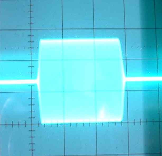
The following pictures capture the envelopes at the four different settings. The horizontal time base is 10 ms. This means that each tick is 2 ms. Please click on a picture for a larger view.
|
ICOM 756PRO CW Envelope as a Function of Rise Time |
|
 |
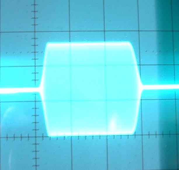 |
| 2 ms Rise Time | 4 ms Rise Time |
 |
 |
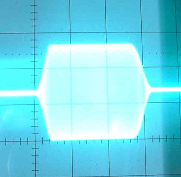
| 6 ms Rise Time | 8 ms Rise Time |
The 2 ms setting appears close to 2 ms. The 4 ms setting measured at closer to 3 ms. The 6 ms setting measured at 4 ms. The 8 ms setting measured at 5 ms. The fall times appear slight longer than the rise times. The falling edge also appears more rounded. The ARRL Handbook suggests that the rise and fall times should be measured between the 10 and 90 percent signal levels. I simply measured the entire transition time. The ARRL approach would further reduce the times (since the transitions are approximately linear, the ARRL value would be 80% of my value).
The envelope is in the approximate form of a vertically mirrored trapezoid, with linear sloped transitions. While the slopes do change with each setting, the corners still provide opportunities for enhancing key clicks.
Measuring the CW envelope is not the only way to measure CW performance. An excellent measurement tool is the spectrum analyzer. Unfortunately I do not have access to one. In the end, the practical judge of key clicks is a receiver. In these tests, I used my second receiver, which is an ICOM 706MKIIG. I have the 350 Hz (FL-232) filter installed in this radio, and used it in these measurements.
I coupled a small amount of energy from the transmitter output cable to the receiver. The transmitter was operated at full power (approximately 110 watts) into a dummy load. The frequency was again set to 7.050 MHz. The signal level was adjusted with the step attenuator to provide an S9 + 10 dB signal when the receiver was exactly on the transmitter frequency.
I tried a few different test scenarios, looking for one that would highlight the effect of the rise time setting. In the end, I settled on the following test. I began with the receiver set to the transmit frequency. I sent a constant stream of dits. I then lowered the receiver frequency by exactly 1 KHz, to 7.049 MHz. I changed the frequency over a few seconds, and then sat at the lower frequency for a few more seconds. I brought the 706MKIIG audio into my computer sound card, and captured the audio as a .wav file. I converted these files into the compressed mp3 format. The four audio files are available in the links in the following table. You will need an mp3 player to listen to these files. Each file is approximately 240 KBytes in length.
To my ear, the rise time setting made a substantial difference in the key click level.
While I had the second receiver connected and monitoring the 756PRO frequency, I spent some time transmitting what I consider to be typical QSO fragments into the dummy load. I tuned above and below the transmit frequency, and selected the different 756PRO rise time settings. It was clear that the 8 ms time was definitely the cleanest, and the clicking became worse as the rise time decreased. Much of what I was hearing reminded me of the soup that I often hear on the bands. Even at the 8 ms setting there would occasionally be some random clicks that would appear. It was sometimes true that the very first dit or dah of a transmission had more click, but sometimes the click would occur for what appeared to be no good reason. In any case, the 8 ms setting made a substantial difference. When right on frequency (and the tone is dominant), the 8 ms setting was also the most pleasant to listen to. At the rise time decreased, the signal became more sharp and shrill. I would definitely experience ear fatigue if I had to listen to the 2 ms setting for any length of time, even if there were no clicks at all.
Since not all readers may be able to play mp3 audio files, I used the Spectrogram, audio spectrum analyzer program to display the waveform of the 2 ms and 8 ms envelope rise time settings. I set the receiver radio (ICOM IC-706MKIIG) to the 2.4 KHz filter setting, so as to capture a wider region of spectrum. As before, the audio output of the receiver was routed to the input of my computer sound card, and then analyzed by the software.
 |
2 ms Audio Waveform |
 |
8 ms Audio Waveform |
An audio spectrum capture will probably not be as useful as an RF spectrum capture, but the existence of the wider signal at the faster rise time is obvious.
The 2003 CQ 160 Meter CW contest took place shortly after I wrote the first version of this page. This seemed like a good opportunity to listen to a large number of CW signals. I decided to tune the band during the contest and note signals that represented either ones with relatively more clicks, or relatively fewer clicks. I used my ICOM 756PRO radio, with a 350 Hz CW filter.
After about 2 hours of listening spread across the two evenings, I had written down the callsigns of 7 signals that I felt were relatively free of clicks, and 20 signals that seemed to have more than an average amount of clicks. This is obviously a very subjective test. One interesting part of this experiment was that I had no idea what transmitters were being used.
A few days after the contest ended, I tried to find as many email addresses for the stations as I could, and I sent them an email and asked them to tell me what radio was in use during the contest, and if it had any modifications. I received the following radio information.
| TenTec Omni 6+, Yaesu FT-1000D (no mods), ICOM IC-781 (with mods), FT-1000D (W8JI mods), ICOM IC-781 (no mods) | Yaesu FT-1000MP (no mods), ICOM IC-765, Yaesu FT-1000D (no mods), ICOM 756PRO2 (4 ms Rise Time), ICOM 706MKIIG, ICOM IC-765 |
| Less Clicks | More Clicks |
Each radio entry represents a single radio. In other words, I am not summarizing by radio, and leaving off the instance count. The ICOM IC-765 appears twice on the more clicks list simply because there were two reported instances of that radio. Since there were so few radios involved, I simply listed each one, and didn't need to summarize.
The email I sent to the stations did not indicate which list they were on. Even with that neutral question, the reply rate for the less click stations was 71% but only 40% for the more click stations. Perhaps this was a study in human nature, as opposed to clicks?
Since the ICOM 706MKIIG ended up on my more clicks list, and since I have one, I decided to capture it's envelope.
 |
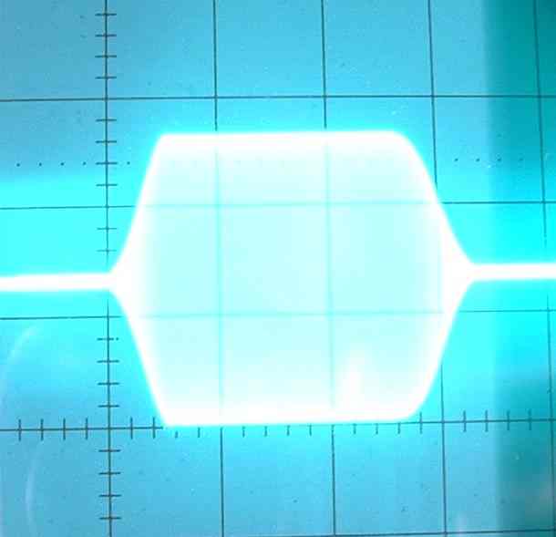
| ICOM 706MKIIG CW Envelope |
As before the horizontal time base is 10 ms per division, so each tick is 2 ms. The rise and fall times are on the order of 2 ms. While the trailing edge has some curve as is terminates, the other transition points are far more sharp. It's not unreasonable to deduce from this picture that clicks are present.
The ICOM 756PRO default CW Rise Time is 4 milliseconds. On my radio, the measured times were lower than the specified times. Given the results of these measurements, and the comments on the W8JI page, I have set my time to 8 ms. The actual delay appears to be under 8 ms, and values under 5 ms are cautioned against by the ARRL.
The ARRL web site includes the published 756PRO review, as well as the extended review. You must be an ARRL member to view these reviews online. The original review was published in the June, 2000 issue of QST. In that review, the CW transmitted signal was described as outstanding. Mention was made of the keying adjustment, but no details were given.
The question becomes: does my radio click? I don't believe that there is a simple yes or no answer to this question. All radios click, it's just a question of degree. What amount of energy is scattered over what spectrum space? Practically speaking, I like the following click test definition. When a receiver is tuned off of the frequency of a CW signal, the clicks should die out at the same time as the detected tone itself. This test doesn't demand a certain receiver or receiver bandwidth. According to this test, my 756PRO is acceptable at the 8 ms rise time, and not at any of the other settings.
Even if the clicks coming out of your transmitter are low, a poorly adjusted or defective amplifier can degrade the signal that leaves your transmitter. If you want to produce the highest quality CW signal that you can, be sure to consider your amplifier as well as your transmitter.
Shortly after I created this web page, I exchanged several emails with Rob, W8LX. If that callsign looks familiar it's because I mentioned Rob on my 756PRO CW Filter Shape Selection page. He helped me understand the undocumented capabilities of the 756PRO receiver with respect to CW filter shape factor. Rob will ragchew at 35 WPM and sprint up to nearly 70 WPM, and clearly understands how to get the most CW performance out of a radio, and the subtle issues surrounding key clicks. The gist of those emails is captured in these further thoughts on CW key clicks.
Earlier on this page I presented a receiver-based test for determining if a transmitter is generating key clicks. I said that the clicks should not extend beyond the detection of the fundamental envelope (tone) in the receiver. My ICOM 756PRO comes very close to that standard at the 8 ms rise time setting. That standard is perhaps too conservative, for several reasons.
The first reason is that under certain conditions, harder keying, which would fail my test, does indeed increase the ability to copy the signal. Rob has documented this with sound recordings, and the idea is captured in many editions of the ARRL Handbook. The circumstances are under marginal and fading conditions. The phenomena is also connected to code speed. Faster code requires harder keying to work through marginal conditions. So, there are circumstances where harder keying, which will certainly equate to a wider signal, will also increase readability. In no way does this mean that clicks are good. It's simply that the test I gave is so conservative that it does not allow for the value of a small, appropriate, and responsible amount of hardness.
A second reason is an interesting but also sad commentary on the current state of this problem. Let's say that you are operating a very clean CW transmitter, and having a wonderful QSO on a clear frequency. A station with a clicky transmitter, but perhaps chock full of narrow receiver filters decides to operate nearby. Due to his narrow filters, and your clean transmitter, he doesn't hear a thing, and decides that is a great frequency to start up a contact. Unfortunately, while he can't hear your clean transmitter, you certainly can hear his clicks. Although you were there first, and are operating with a higher quality signal, you get stomped on. I am reminded of the phrase road hog. If your transmitter is substantially wider than your receiver, you will always run the risk of stomping on nearby QSOs. Goodness know that we have been in a period where narrow filters are flying off of the manufacturers shelves, and transmitters are producing signals with unnecessary width. So, hardness which in the extreme becomes clicks, can also create a buffer zone around your signal which keeps others from stomping on you.
On the 756PRO, the conclusion appears to be that operating at the 8 ms rise time setting will produce the narrowest signal, but one that will not be as effective as it could be under marginal conditions. At 8 ms, you also run the risk of clicky stations getting close enough to QRM you without even knowing it. If you reduce the rise time setting, the harder keying may make you more readable (especially if you are a high speed operator). When the readability no longer increases, any additional reduction in rise time simply makes you consume more bandwidth for no good reason, except perhaps to encourage clicky transmitters to stay further away. It's better that they just not click to begin with.
Back to my Experimentation Page