 |
 |
 |
| ICOM IC-718 VFO Encoder Replacement by Jim, AD7UZ | ||
Greg Ordy
Note: This story was updated in March of 2009 when it was learned that the parts I purchased were directly usable in the ICOM IC-718 and ICOM IC-910. Please click this link for a description of this repair, and the availability of encoders. A further update took place in May of 2012.
Note: This story twists and turns at the end, so please read all of this page,
Around the spring of 2000, the rotary shaft encoder in my ICOM 756 developed a problem. This is the primary VFO control. A portion of its rotation would not change the displayed frequency. It had a dead zone. The problem increased in severity until approximately 90 degrees of rotation were dead.
It seemed as if the obvious solution was to replace the part. ICOM (Bellevue, WA) does indeed sell the part (their number 91510606). The cost, however (at the time of writing this page), was $130 (USD). Since that seemed rather high, I decided to explore alternatives.
The first alternative was to repair the defective encoder. It appeared as if the problem was due to some sort of contamination. Many encoders are based upon optical slots in a rotating wheel. A small piece of lint or even hair might disrupt the normal operation of the encoder. I decided to take mine apart.
Getting at the encoder is not fun. Even after the front panel is unscrewed from the chassis, it is still connected by several delicate multiwire cables. It's very easy to damage the radio while removing the encoder.
Finally, the encoder was hanging from the radio by its 4 wire interface cable. The encoder looks much like a common potentiometer. In fact, as I pried open the metal case, I fully expected, even hoped, to see a slotted wheel with a LED/optocoupler assembly across it. I wanted to find some lint, or other contamination, clinging to part of the wheel.
I was more than surprised when the contents of the case turned out to be a solid wheel surrounded by a printed circuit board with two integrated circuits, and a number of surface mount passive components, including miniature trimmer pots.. This was no simple encoder. It was a highly integrated and complex subsystem.
While the circuit board and its supporting structure obscured most of the rotating wheel, I was able to gain limited access to it. I used a combination of cleaning sprays and compressed air on the wheel. When I next turned on the radio, the encoder worked perfectly. After about 6 hours, however, the encoder again started to fail (the dead zone returned). I resorted to more spray and air. While the dead zone did permanently go away, the control did develop jitter in the least significant digit. This is much better than the dead zone problem, but it is not perfect.
So, with only partial success in repairing the encoder, I again looked into obtaining a replacement part.
The ICOM schematic showed the part number to be RMS20-250-201-1P. I didn't know if this was an ICOM number, or the number of the manufacturer. The encoder metal case duplicated this number, along with the name Copal. I was fairly confident that I now had the manufacturer's name and their part number. I got on the Internet, and in less than two minutes, I was looking at a specification sheet for the encoder.
The encoder is indeed an impressive part. Please check the specification sheet for details. It is a magnetic encoder as opposed to optical. Each single revolution of the shaft produces 500 output pulses. At the standard tuning rate of 10 Hz/pulse, one knob revolution changes the frequency by 5 KHz. I talked with a factory representative and learned that there was no specific or recommended cleaning/adjustment procedure. I also learned that the part is not stocked in the United States (except by folks such as ICOM, who purchase the part for their own use and consumption).
It is possible, however, to order the part directly from their (Copal) California office. In quantities of 10, the price per part is $26. In quantities of 100, the price per part is $22. The bad news is that there is a 12 week delivery delay.
Given the lack of success in cleaning the original part, and the replacement cost from the manufacturer, I decided to order 10 parts. I am writing this page while awaiting delivery (estimated at June, 2000). I will be installing one encoder in my 756, and keeping a spare one on the shelf for my 756Pro. It appears to use the same encoder. The remaining parts have been promised to other 756 owners with similar encoder problems.
NOTE: The information on this page was gathered in March, 2000. Prices and other data may change over time. I will not be held responsible for damage done to your radio as a result of reading this page. I have provided this information so that others with the same problem can have access to my experiences. If you decide to open your radio, at the least, obtain the appropriate ICOM service manual. I've also been told to work with one hand in your pocket...
EPILOG: Copal did indeed send me 10 encoders a few days ahead of schedule. I installed one in my 756, and it worked, electrically, perfectly. While putting my radio back together, however, it became clear that the new encoder shaft was 1/2 inch too short! I rechecked that I had ordered the part number obtained from both the ICOM schematic and actual encoder case. They matched. I then started to more carefully check the Copal data sheet. Indeed, their data sheet described a part with the shorter shaft. I had been so concerned about the electrical interface, and because the part numbers were an exact match, I just didn't pay attention to the shaft length.
I contacted Copal, and it turns out that they made a special batch of encoders just for ICOM. These encoders have the same Copal part number but a longer shaft. In addition, Copal could not even sell me the part, claiming that they sold all of the stock, and were not set up to make any more. I suspect that ICOM specified a special variation on a standard part and then Copal built them a custom batch. So, as of this writing (September, 2000), the only place where you can purchase a long shaft encoder is from ICOM. I have been working on schemes to extend the encoder shafts I have, and I believe that the shorter or normal shaft encoders are used in the ICOM 706. Still, the lesson here is that you can never do too much checking...
[I have since acquired a 706MKIIG, which is a fine radio. It does not use the short shaft encoder. I do believe that the 756PRO and 756PROII use the same encoder as found in the standard 756]
Update: July, 2002. I was contacted by Wolf, DJ3TZ concerning this issue. Apparently the Kenwood TS-850 uses a Copal encoder which is nearly identical to the ICOM 756. Wolf was also experiencing erratic frequency tuning, which became worse over time. Wolf was clever enough to experiment with the trimmer pots in the encoder. He found that his problem was due to a marginal alignment of the encoder. By adjusting the trimmers within the encoder can, he was able to regain complete functionality! So, if you are experiencing frequency jumping and jitter in the last digit, perhaps you have an encoder which has drifted out of alignment. Wolf gave me permission to reprint his experience on this page. Here it is. Thanks Wolf, this sounds like it might be the real problem, and it's easy to fix, if you're willing to open up the radio and spend some time.
Hi Greg, Many thanks for all the valuable information you provide in the ICOM 756 VFO Encoder Saga! I found your page while searching for information about the COPAL RMS20 encoder. For a long time, my Kenwood TS-850 had the problem that while turning the main frequency dial, the frequency would stop changing with the last digit jittering. For several years, the problem occurred so rarely that it did not really hinder operation, and I saw no chance to locate the problem. Recently, however, the problem became more serious, making the radio almost useless. Using the 850's service manual, I was able to locate the encoder and its connection to the radio's main data bus. The encoder has two data outputs, A and B. Both carry digital signals at 5V level. Its frequency depends on the rotation speed and the signals differ in phase to allow for clockwise/counterclockwise detection. Together with my friend Theo, DJ9PK, I observed these signals with an osciloscope. One of them vanished whenever the the frequency stopped changing. Taking a look into the encoder, we tried to locate any kind of mechanical problem, perhaps a little bit of dust, but there was none. The encoder consists of a magnetized wheel and an magnetoresistive Hall sensor, in addition with some electronics. Checking the signals from the sensor revealed that is analogous. It consists of a voltage of approximately 2.5 V DC plus approximately 80 mV AC when turning the shaft. We found that the amplitude of the AC voltage strongly differes while turning the shaft. The reason is perhaps that the magnetic field produced by the wheel is not constant, but seems to depend on its position towards the Hall sensor. The amplitude seems also to depend on other, unknown factors. The PCB inside the encoder has an IC that obviously works as a comparator and digitizes that input. Checking its 8 pins revealed that two carry the input coming from the sensor, two carry the digital output, and two pins are connected to reference voltages. These reference voltages can be adjusted with two variable resistors on the left and the right of the IC. Turning one of the resistors fully into one direction causes the digital output to become constantly low or high, respectively, because the reference voltage then is always higher or lower then the sensor signal. Within a range of 10 or 20 degrees, the comparator works as intended. I suspect that the reason for the occasional failure was that the amplitude of the AC signal was sometimes below the comparator's reference voltage, thus causing the output to stay high or low. Rotating the shaft by hand but at a constant speed and observing the digital output on the scope allowed us to adjust both resistors so that encoding now works fine. Here is the pin layout of the IC: 1 Output B 2 Reference voltage B 3 Input B from sensor 4 Gnd 5 Input A from sensor 6 Reference voltage A 7 Output 8 + 5 I hope this information will be helpful to you and others. Feel free to provide this information in any way you find useful. vy 73, Wolf DJ3TZ |
|
Wolf, DJ3TZ, Encoder Experiences |
If you read the first part of this page, you know that I set off to find a less costly replacement for the VFO encoder in the ICOM IC-756. I purchased 10 encoders from the manufacturer, Copal, only to then discover that the ICOM parts were a special batch with a longer shaft. Over the next few years, I sent out a few parts to brave experimenters who wanted to see if they could modify the part for service. At best, this is a lot of work.
At the beginning of March, 2009, I received an email from Jim, AD7UZ. Jim has an ICOM IC-718, and his encoder was damaged due to a static discharge. He did all of the research and legwork on the encoder, and discovered that the parts I had purchased, while not a drop-in replacement for the ICOM IC-756, were a drop-in replacement for the IC-718, and it appears, the IC-910.
I sent Jim a part in the mail, and it indeed dropped right in and works great. Looks like I had the right idea, but just the wrong radio, and was about 10 years too soon!
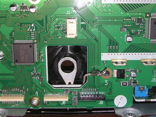
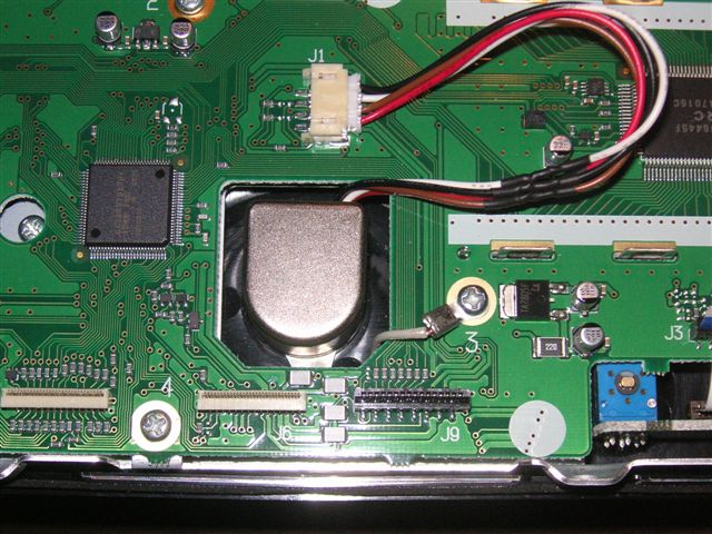
Jim's experience suggested that the failure of the original part was due to a static discharge from his hand, through the VFO knob, and then into the encoder. In order to reduce the chances of this happening again, he added a grounding ring to the encoder shaft, so that the encoder case would be grounded, and any static energy would not go through the encoder, but rather around it. Here are some pictures that Jim sent me of his repair procedure. Please click on a picture for a larger view.
|
|
|
|
| ICOM IC-718 VFO Encoder Replacement by Jim, AD7UZ | ||
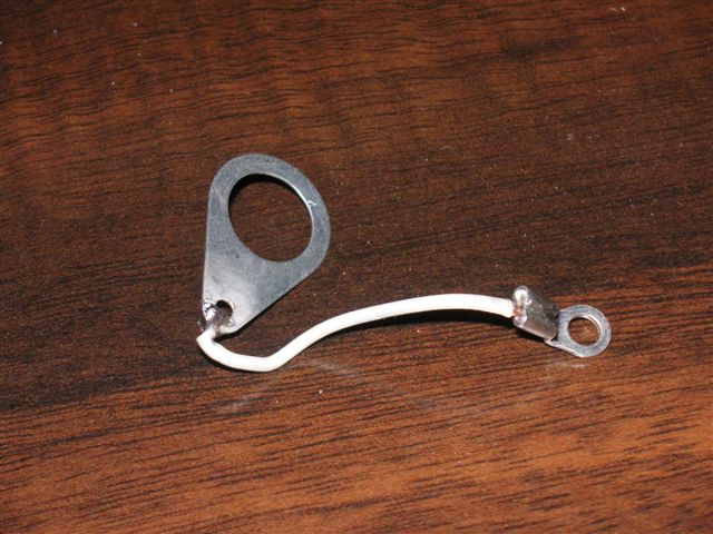
Jim added the grounding ring shown in the right picture. He had to file down the sides of the larger ring (HH Smith 1497 ground lug) to fit within the molding of the case. This can be seen in the left picture. The encoders are shipped with wire pigtails, and the connector must be reclaimed from the original part, and attached to the 4 wires coming out of the replacement encoder. The heat shrink tubing over the splices can be seen in the middle picture.
The smaller (#4) ring terminal is attached to a mounting screw on the PCB that is grounded. The terminal needs to be bent up and away from the board so that it does not touch any of the traces under it.
In March of 2009, Icom is charging $98 for the replacement encoder, order number: 6910012480, description: Sensor RMS20-250-201-1R. I still have several from the batch of 10 I purchased. I'm happy to make available the ones I have left for my cost plus shipping. That is approximately $30 (USD). Priority or rush postage probably adds a few dollars. I will only sell them one at a time, since I'm not looking to become a one-time distributor to another middleman intending to make a profit. If you have need of this encoder, please email me. [NOTE: I am now out of encoders. Please read the next section]
My thanks go to Jim for discovering this synergy.
It's been almost 10 years since I started this page. The topic was very inactive until 2009, when I started to receive a number of emails. At this point, with 2010 just a week away, here's what I've learned.
The ICOM 718 does appear to have a design issue that causes encoders to become defective at a much higher rate than the same basic part in other radios. Jim, AD7UZ, probably identified the issue, and his solution of the added grounding strap seems like a good idea.
In the case of all other ICOM radios, I now believe that it is very rare that the encoder truly breaks. I believe that in these cases, the encoder drifts out of alignment. This is as described in the previous text from Wolf, DJ3TZ.
Folks have sent me their nonfunctional encoders, and I've been able to successfully align then back into normal operation. The alignment consists of a very small adjustment to one of the variable resistors on the encoder PCB (see the picture below). If you do not have an ICOM 718 radio, then I strongly suggest that you attempt an alignment, especially before spending what is now around $100. If you want, email me, and I'll be glad to try to align it here. All that will be involved is the shipping costs.
If you have an ICOM 718, then odds are much higher that your encoder is actually busted. But, my guess is that what has blown out is the single 8-pin IC on the main encoder PCB. The part is the Toshiba TA75393FB, surface mount dual comparator. Seems to me that replacing this single IC should be much cheaper than spending $100 for a new encoder. To date, I've been unable to test the IC replacement approach since I've not had access to a broken encoder. I would like to ask anybody with a broken encoder to email me, and I would like to arrange to have you send me the encoder. I would attempt the repair, and hopefully verify a new alternative for folks with broken encoders. It's that, or, pay ICOM $100.
Finally, here's a picture of what we are talking about. Roberto, EB4EQA, kindly forwarded me this excellent picture of all of the parts inside the encoder from his IC-910H radio. He needed to take it apart to clean the shaft and restore normal smooth turning operation.
The single 8-pin IC and the two subminiature potentiometers can be seen on the PCB. The assembly in the lower right is the magnetic pick-up. The surface with the label M121 sits next to the wheel that has 250 embedded magnetic regions. As the shaft spins, the magnetic pulses are picked up, and drive the encoder outputs.
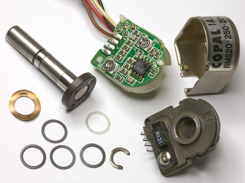 |
| COPAL RMS20-250-201 Encoder, picture courtesy of Roberto, EB4EQA |
There have been a few noteworthy developments in recent months. First, I exchanged email with a 718 owner, David, AC8HV, who had a blown up encoder. This raised the question of replacing the chip as a way to fix the encoder. From previous looks at the part, and the information from Wolf, we were convinced that the single IC on the encoder PCB was a rather garden variety dual CMOS comparator, usually available for less than $1. Several Digi-Key alternatives looked promising, including:
The 2903 reference further suggested the LM393, and this was the part that was used. The result was a working encoder. So, it does appear to be possible to replace the chip in the encoder, and restore the expensive component to normal operation. After a chip replacement, it might be necessary to calibrate/align the encoder. David wrote up a web page, and it can be found on the AC8HV web site.
I also received this interesting information from Adam Lassiter, KB8UUE.
| I have enjoyed your web site and rotary encoder saga. I
have recently gone through my own and here is what I found.
|
|
Adam, KB8UUE, Encoder Experiences |
Adam's work shows that going between brands may be a way to get parts, and, there may be additional sources as well. My bottom line continues to be that paying over $100 for an encoder is not needed. I've concluded that a chip replacement and/or alignment should fix most all encoders. If surface mount repair is not possible, then searching for the same part in other radio brands or applications can also lead to less expensive solutions.
Although the previous sections show that both alignment and chip replacement were possible with the encoder, I wanted an opportunity to try it myself. In May of 2012, I was contacted by a ham out in Nevada, and the bottom line was that I ended up with his IC-718 on my bench with a broken encoder. It appeared to be a victim of a static discharge.
Removing the encoder from the 718 was not too hard. 13 identical screws remove the top and bottom covers. 4 more screws release the front panel. To completely detach the panel would require removing some push in cables, but, I found that I could simple rotate the panel up and over the top, exposing the encoder without disconnecting a single wire or cable.
Once out, I connected the encoder to a microprocessor test jig that I had used a few years ago.
 |
 |
 |
| ICOM IC-718 VFO Encoder Replacement at W8WWV | ||
The picture on the left shows the test fixture. It's an LCD display driven by a microprocessor. 4 wires connect the encoder to the microprocessor. One wire is +5 VDC, one is ground, and the remaining two are the signal lines.
A quick word on the signaling from the encoder, which is often called a quadrature encoding.
Decades ago, when I first heard of using encoders to change frequency (via a microprocessor and DDS chips) as opposed to a variable capacitor, the picture that was often given was of a disk with slits and a light shining through a slit, onto a detector. When the disk rotates, the output of the photo detector would be on - off - on - off - on - off - etc. The Copal encoder uses a magnetic pickup as opposed to optical, but it's the same concept.
Fine. If you think about it for a few seconds, you realize that such a simple scheme can detect movement, but can't tell the direction of movement. on - off - on - off looks the same as off - on - off - on. For a system that can only rotate in one direction, perhaps a factory conveyor belt, this would not be a problem. It is a problem for a VFO knob, since we want to turn it in both directions. Since we are going to connect the encoder to a digital microprocessor, the on - off - on is perhaps better stated as 1 - 0 - 1. on is 1 and off is 0. If we can't encode both change and direction on a single wire - what should we do? Well, the most obvious idea is to add a second signaling wire. That's what these encoders do. Now, in a digital sense, we can encode or create a 2-bit number, which has 4 values, 0, 1, 2, and 3. The quadrature description refers to the number four, and we do indeed have four output states. So, with 1 bit or 1 wire, we can encode 0 and 1. With 2 bits or 2 wires, we can encode 0, 1, 2, and 3.
When the encoder is turned in one direction, the output is 0 - 1 - 2 - 3 - 0 - 1 - 2 - 3 - etc. In the opposite direction, the sequence is 3 - 2 - 1 - 0 - 3 - 2 - 1 - 0 - etc. Now, we have encoded both change and direction. It's really not that complicated. The program running on the test microprocessor detects changes in the lines, and given the previous state and the current, you can figure out the direction.
When the encoder was removed from the radio, it was found that one of the signal wires was going high and low (1, 0, 1, 0, etc), but the other did not change. The chip is a dual comparator, and one section drives one wire, and the other drives the second wire. So, it's quite likely that a static discharge took out 1/2 of the chip.
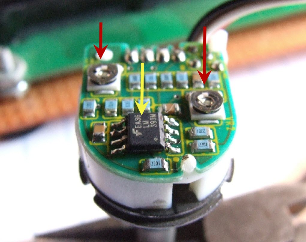
Once I verified that the encoder was broken (and not something else in the radio), I removed the metal can, and set about replacing the chip. I used an LM393 from Digi-Key, costing all of 40 cents (in quantity of 10). The chip is shown in the middle picture. Red arrows point at the two alignment pots, and a yellow arrow points at the LM393. I did experiment with the alignment pots, but I found them very forgiving, and they ended up where they started off.
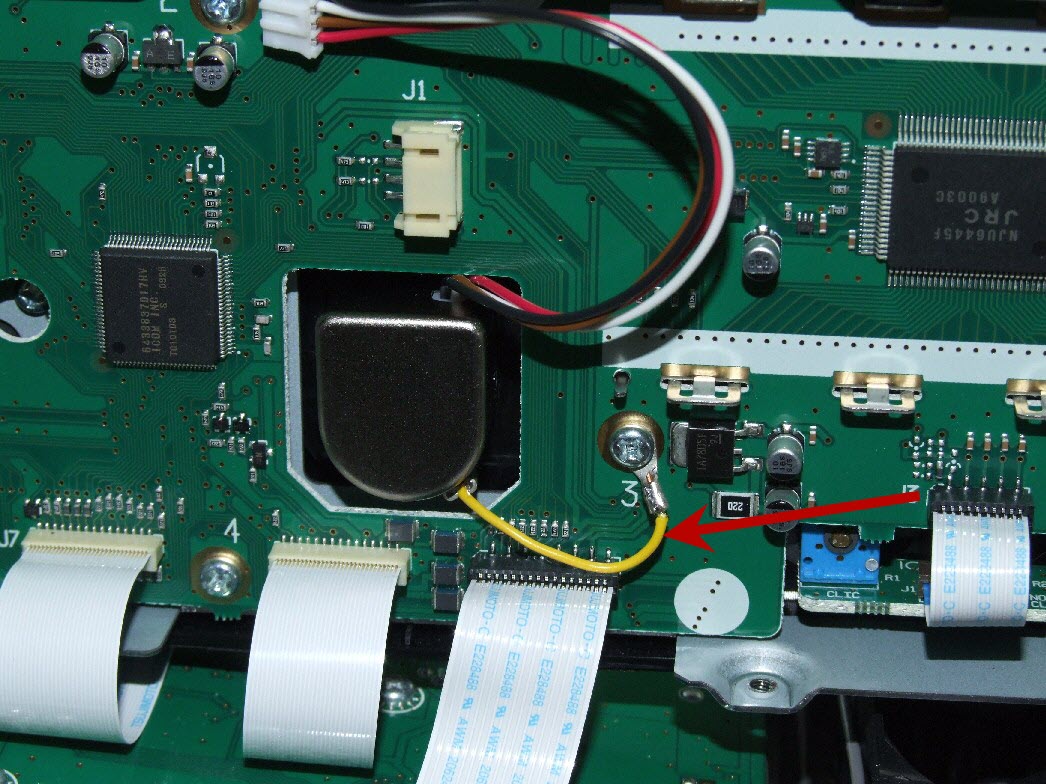
Before putting the radio back together, I put a short grounding wire from the encoder shaft to a nearby ground screw. This is shown in the right picture, and was described in an earlier section. The encoder is mounted on the plastic front panel. If a static discharge were to jump from the hand to the knob and encoder, it would have to exit via an encoder wire. There is no other low impedance path.
So, if you have a Copal encoder in your radio, and it fails, there is no good reason to spend $100 plus for a new encoder. The chip is probably the problem, and replacing it is not that hard.
Back to my Experimentation Page