 |
 |
| Original Junction Box | Original Box Wear |
Greg Ordy
This page describes the junction box which is mounted at the base of my tower. I wrote the page mainly to document what's there, for when future maintenance is required. Perhaps you will find something interesting here, or have a suggestion for an improvement to what I have put together.
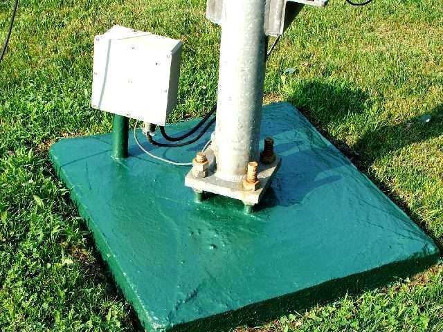
My tower is a 55 foot US Tower MA-550. It mounts on four, one-inch diameter threaded rods embedded in a concrete base. The tower is located in the middle of a grassy area that is mowed. When I poured the base, I used a wooden form at the ground level to provide a neat concrete square with a sloping top to promote drainage. One of the lessons that I've learned, especially when it comes to landscaping, is that it is very important to minimize maintenance. In this case, I knew that I wanted to be able to cut the grass right up against the concrete base, and be able to use a string line trimmer to achieve a finished look.
This meant that the cables going back to the house needed to buried, and emerge up through the base itself. No cables could touch the ground, even to disappear underground next to the base. Even a simple piece of conduit strapped to the base would be in the way of the mower deck, or catch the line of the trimmer.
When I was pouring the base, I embedded a 1.5 inch diameter metal pipe with a 90 degree long sweep elbow into the concrete. This allowed the cables to enter the base underground, and come up over the base itself. The cables consist of a coaxial feed line, a rotator control cable, and two heavy gauge copper wires which connect to two 8 foot ground rods which are installed a few feet away from the base, completely buried underground. The end of the metal pipe is threaded, and wide conduit lock nuts are used to trap the plastic case on the pipe.
My first mistake was not allowing much room for future expansion. The only unused wires were three wires in the rotator cable. Whenever possible, add more wires and cables than you immediately need, since odds are that sooner or later you will.
The initial cables coming down the tower included the single feed line for the Sommer XP-50 antenna, and a rotator control cable for the Yaesu G-800SDX rotator. I use 8-wire heavy duty rotator cable, although the Yaesu rotator only requires a 5-wire connection.
I mounted a plastic utility box directly on top of the pipe, as it came out of the concrete base. This junction box provided the convenient place to join the cables going to the house with the cables going up the tower. It was also a place to locate lightning protection and grounding devices.
The box has been in service approximately 7 years. The box is made by Carlon, and is designed for outdoor electrical use. The cover has a gasket to prevent water from entering the box. The UV damage from the sun has now taken its toll, and the molded plastic case has cracked around many of the screw holes. Sooner or later, it will be very easy for water to penetrate into the box, and then more trouble will surely follow. It was time to replace the original box.
|
|
|
| Original Junction Box | Original Box Wear |
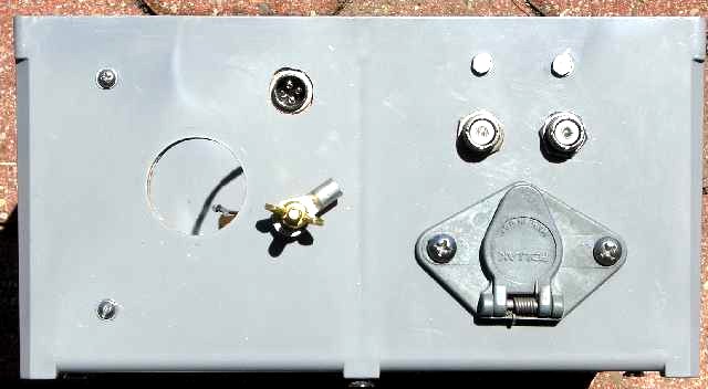
The original junction box is shown in the left picture. Please click on a picture for a larger view. All of the entrance holes in the box are located on one side of the box, which points downward in this application, since the box is mounted vertically. This helps keep water out of the box, since there are no access holes on a top or vertical face. The two cables going up the tower can be seen coming up to the bottom of the box. The coaxial cable terminates in a PL-259 (UHF) plug. The rotator cable connector I used was made for automobile trailer wiring. It's a waterproof connector with high current contacts. I found it at the local hardware store. A third wire enters the box, and that is a ground wire (#4) which connects directly to the tower, under a second nut on a threaded rod. The last connector is a 4-pin microphone connector that was used to bring the unused three rotator controls wires out of the box. More on this later.
The right picture shows the wear and tear on the original box after I took it out of service. Many cracks are visible in the picture. The large hole on the left side accepts the 1.5 inch pipe. The connector hole on the upper right side holds the trailer connector which passes the rotator control cable. The hole in the lower right corner is for the SO-239 (UHF) connector for the coaxial cable. The tower ground wire entered through a hole in the box.
The original and new boxes are both made by Carlon. They produce a wide range of outdoor-rated boxes with lid gaskets. These boxes are available from home supply stores, such as Home Depot. A full-service electrical supply house will probably carry a wider range of box sizes. The original box measured 8" X 8" X 4" (inches).
The original box contained a PolyPhaser IS-RCT rotator cable lightning suppressor, and a PolyPhaser IS-B50LU-C0 coaxial cable lightning suppressor. The coaxial cable suppressor, which featured a bulkhead mount, was attached directly to the bottom of the box, and provided the external transition to the feed cable going up the tower.
When I planned the tower, my goal was to have a simple installation with a single rotating antenna on top. I picked the Sommer XP-50 so that I could cover all of the HF band at and above 14 MHz with a single antenna. In order to support this plan, I needed a single coaxial cable, and a single rotator cable. These cables needed to run almost 200 feet back to the house, and would be buried underground. I had previously had good luck burying cable using a manual technique that used a large spud bar and a special oak push stick. The cable was buried only about 6 inches deep, but for my yard, and how the area is used, that's an acceptable depth. One problem with this technique was that it was easiest to bury two cables in the slit formed by the tools. If I would have used a standard trench digger, such as a Ditch Witch, I would have run a number of extra cables. But, since I was going the cheap, simple, and manual route, I could only bury two cables - the coax and the rotator control cable.
It appears as if the best way to bury a cable is with a vibratory plow. Manual slit trenching is work, and a typical Ditch Witch makes a 4 inch wide trench which displaces an awful lot of dirt. A vibratory plow makes a narrow slit in the ground, and automatically feeds a cable into the slit. Recovery from the procedure is immediate, no grass seeding is necessary, and there is no wide trench that might settle into a depression.
I mentioned that I did not do a good job of planning for future expansion. I ended up getting interested in 6 meter operation. I was able to add 6 meters to my Sommer XP-50 with an accessory element kit, but now I wished that I would have run a lower loss transmission line. The cable I ran is Davis RF Bury-Flex (9914F). In retrospect, with 6 meter operation in mind, I wish I would have run something like LMR-600DB.
I've only ever had the Sommer Yagi at the top of the tower, but I have hung wire antennas off of the tower. My first wire antenna hung off of the tower was a pair of phased 40-meter delta loops. This antenna required two relay control signals. The first to operate a remote coax switch so that I could select the Yagi or the delta loops. The second control signal reverses the direction of the delta loop array. Fortunately, I did have 3 extra wires on the rotator control cable, and those were used to provide two 12 volt DC control signals (with a shared ground) that can be controlled back in the radio shack.
The 4-pin microphone connector on the original box is used to bring out these three control signals. My first coax switch was a homebrew switch that had poor port to port isolation. While this provided a short term solution, I knew that sooner or later I wanted a higher quality remote coax switch, and one that could be integrated into the junction box.
Life would have been simpler if all I needed to do was to replace the original box with a new one of the same size. Times have changed, and my needs have changed, and the new box needed a few new functions. In particular, I wanted a two-position remote coax switch in the box. This would require a larger box. Since I was shopping at my local home improvement center (OK, Home Depot), I only had a single choice for a larger box. This box measures 12" X 12" X 6". I did not need a box this big, but it was my only choice unless I wanted to drive around to the electrical supply houses that service the trades.
I searched around for an appropriate coax switch. It needed be able to switch 1500 watts at HF, and also possess good isolation and low loss at VHF, should I ever get interested in 2 meters (finally, some planning ahead). The relay coil needed to be a 12 VDC coil, since that was my standard switching voltage. I settled on the Tohtsu CX600NL,which I obtained from RF Parts. The relay had all of the right specifications, but was expensive, at $95 (USD, 2005), and also used N connectors, as opposed to UHF connectors.
In the original box, I had a single lightning suppressor for the single output cable. The new box will have two outputs after the switch. I had a choice. I could either stay with a single suppressor and put it at the input to the switch, or, buy a second suppressor, and locate them at the outputs of the switch. With a single suppressor at the input to the switch, I would be exposing the switch to more damage, since the switch would be between the antennas and the suppressor. With two suppressors, I would have more protection, and more isolation for the switch, but, I had to buy another suppressor. The suppressors were not cheap either - at $62 (USD, 2005). I ended up getting a second suppressor. Part of the reason was that the suppressors were designed for bulkhead mounting, and a pair of them, side by side, would get me out of the box, and also provide a solid mounting point for the switch. In other words, the suppressors would mount on the box, and the switch would mount on the suppressors. This solved all of the mounting problems for the switch.
 |
 |
| New Box Bottom | New Box Contents |
The left picture shows the bottom of the new box. As before, a 1.5" hole mounts the box to the pipe coming out of the tower base. A 4-pin microphone connector was again used to bring out the control signals. I always seem to be experimenting with antennas, and having handy control signals to switch bands or directions is always desirable. On this box, the ground wire going to the tower will terminate in a ring terminal that is attached to a bronze stud with a wing nut. This is a little more flexible than just putting the wire through a hole in the box. The two coax connectors are located side by side, and in front of the trailer connector which carries the rotator control signals.
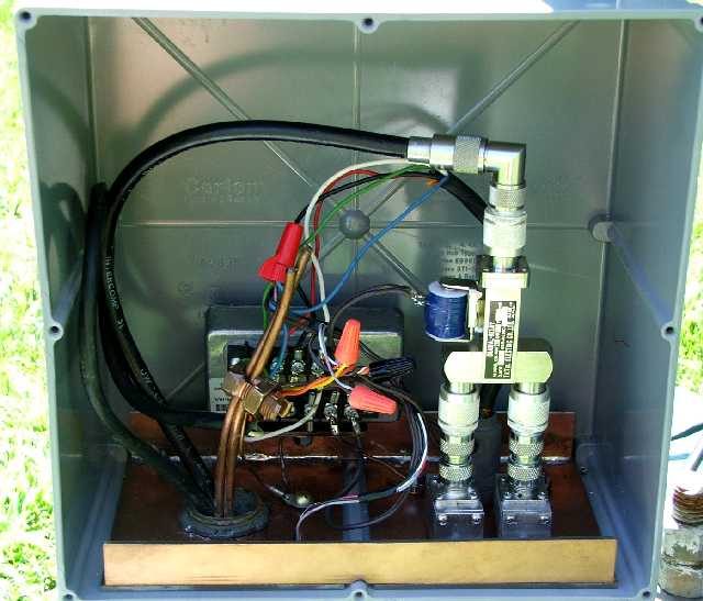
The right picture shows the inside of the box, after it was mounted on the pipe. The transmission line going back to the house goes through a UHF elbow, and then a UHF/N adapter. Two N/UHF adapters are located on the output of the switch, and UHF male to male adapters get the gender correct going into the lightning suppressors. That Christmas Tree of two suppressors, one switch, and 6 adapters costs approximately $250 (USD). I didn't expect to spend that much on this project, but I do have a good quality switch, and lightning suppression for each line. In order to compute the total cost of the junction box I need to add in the cost of the rotator cable surge suppressor ($54 USD), and the box ($26 USD). I would bet that in most cases, the largest costs in a tower project are the tower, the antenna(s), and the rotator. Still, other parts of a tower project, such as a junction box, can add to the cost. Those accessories do add up.
When assembling the parts, I used a dielectric water proofing filler at all of the internal junctions. This paste is squirted into the connector before mating, and displaces the air that would otherwise be in the junction. The idea is to keep moisture off of the conducting surfaces, and reduce corrosion. I have not used this product before, but it seemed like a good application, since the connectors inside the box will probably sit for years before they are next removed, and I would like to keep them as clean as possible.
The original smaller plastic box did not require any mechanical support other than being attached to the pipe. A swift kick would certainly crack the box and send the pieces flying, but other than that sort of vandalism, the box was self-supporting. The new box is bigger, and it contains more parts. I was concerned that a heavy snow load combined with the weight of the box contents might be enough to crack the box around the mounting point. To provide more support, I fabricated a liner for the bottom of the box. This liner was made from very thick PCB (printed circuit board) stock. The construction of the liner was a little tricky because the box has a rib which extends down the middle of each side. This rib would interfere with a simple flat liner. So, I had to make the bottom of the liner out of two pieces, and join them together with front and rear support sides. The construction is visible at the bottom of the right picture. All of the joints are soldered. This liner provides support for the contents of the box without relying upon the box itself. An added bonus is that the liner acts as a ground plane, and is used for that purpose.
The rotator cable lightning suppressor is located at the back of the liner. It acts as a convenient terminal block where the cable going back to the house is joined with the short pigtail going to the rotator connector, the 4-pin microphone connector, and the relay coil on the switch (the blue cylinder in the picture). Wire nuts are used to splice together shared signals.
This section describes the maze of cables that complete the circuit from the control box in the house to the junction box at the tower base. Don't expect it to make any sense. This just helps my memory when I try to figure out what I did in a few years. The cable from the back of the switch box is a two-wire with shield cable. That cable connects to the rotator cable that goes to the verticals, as well as a white cable to the underside of the deck. The cable going to the vertical switches the 160 meter CW loading coil. The white cable otherwise has control signals for the receiving antenna switch box at the back of the deck. The white cable #1 switch is yellow, and the #2 switch is blue.
Under the deck, three jumper wires go from the white cable to the rotator cable going to the tower.
The 4-pin connector on the box has the following pinouts: #1 - coax switch (beam/vee), #2 - spare (160 CW|ground screen), #3 - GND #4 - GND.
I replaced the box in July of 2005. If not for the UV damage, the box would last nearly forever. My one thought on slowing down the damage is to find a friend who is good with the sewing needle, and ask them to make a box cover out of the cloth-backed vinyl which is a common cover material. Even if the cover only lasted a few years, the box would stay out of the direct sunlight.
Back to my Experimentation Page