 |
 |
| KE9OA Angle View | KE9OA Right View |
Greg Ordy
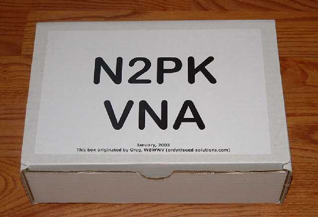
In December of 2003, I volunteered to act as a group parts buyer for 20 N2PK VNAs. Around January 14, 2004, all of the parts had arrived, and had been divided into 20 boxes. I was ready to ship out the individual kit boxes to several group members who would forward them on to the end builders.
If problems or issues are discovered, I will report them in the following dated sections. The most recent report will be first.
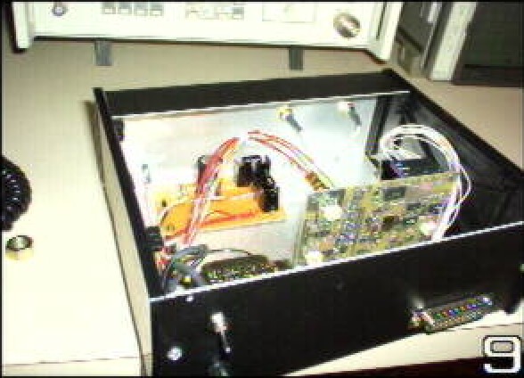
My VNA, made from this batch of parts, is now complete. At this point, I have approximately 20 hours invested in assembly and construction. More details can be found on another page.
Congratulations to Pete, KE9OA, the first person to assemble the VNA board which came from this group build. Exhaustive testing has not been completed, but indications look good that the board works just fine. Pete also had time to put together a linear power supply with special bypassing techniques to keep it clean down to 10 KHz. This sounds like a good companion for the VNA, although Paul, N2PK, also has a power supply design in his second article.
Pete's web site has a number of construction projects, including receiver designs, RF noise sources, and an SSB detector for old receivers lacking one. Perhaps VNA information will end up there as well. Pete sent me the following two pictures. He used a Ten-Tec enclosure for his analyzer. Pete's power supply is available via this link. Please click on a picture for a larger view.
|
|
|
| KE9OA Angle View | KE9OA Right View |
Pete's success, assuming that all testing checks out, indicates that the VNA PCB has the single flaw described in the next section.
NOTE: VNA PCB flaw found. The initial batch of boards from the new supplier in Italy were discovered to have a flaw. This may not be the only flaw, but is the first found. If you received a box (see the pictures below) with my name and callsign on it, then you should have this board and flaw. You should fix this error before attempting to power the VNA. What follows is a description of the flaw and the fix. This flaw only applies to that batch of boards. In particular, it has no relationship to the Bare Bones board.
The flaw is due to a hole which was drilled in the wrong place. By dumb luck, the actual location of the hole happens to ground a trace which was already at ground potential. In other words, the extra hole can be ignored. The problem is the missing hole. The hole was designed to ground a signal. No hole, no ground. There are two choices for a solution. Either drill a hole and ground the trace to the bottom of the board, or, run a patch wire from the trace to a nearly ground.
The hole is intended to ground pin 5 of U280. This is the -5V regulator, and pin 5 is the ground. Although the regulator is conceptually a garden variety three terminal regulator, it is packaged in an 8-pin package.
Here is a picture of the top of the board, in the region of the problem. Please click on the picture for a larger view.
 |
| U280 Pin 5 VNA PCB Error |
The hole marked 1 should have been drilled towards the top of the picture, on the pad labeled 2. Hole 1 is acceptable since the trace is already ground, and the plated hole connects it again to ground on the board bottom. Pin 5 of U280 lands on the upper portion of pad 2. It must be grounded. Either drill an appropriate hole to replace the missing hole, and run a ground wire to the bottom, or, run a wire on the top of the board from 2 to 3, which is also ground.
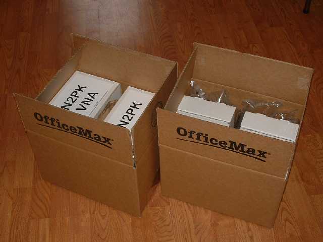
Thirteen boxes were shipped. No news is good news, and there are no known problems. Digi-Key almost upset the schedule, sending me an incorrect connector. I called and told them of the problem, and the correct parts were at my door by 9:00 AM the next morning. Very good service. Did you know that Digi-Key was started by a ham?
The initial design documentation included several spreadsheet tables which described and labeled the parts on main VNA board, and the T1-6T bridge. I took these tables, and added a third table which is an aggregate bill of materials for the VNA and bridge.
It's hard to believe that it would ever make sense to order parts for a single VNA. Nobody wants to sell you a single SMD resistor. Buying in quantities of 25 to 1000 (depending upon the particular part) results in significant discounts. With that in mind, the bill of materials has a cell which specifies the number of units. This number is multiplied by the number of parts of each type per unit, and results in a column showing the number of a given part needed to build that number of units.
At that point, it's necessary to revert to a manual process, and compare the quantity needed against the price break points. My own guess from doing this process once is that numbers between 20 to 25 units have good discounts, which means that you can get a discount, but you don't have to build hundreds of units. Buying for less than 10 units may be painful, due to the various price break points, and the minimum order costs.
Follow this link to download the Microsoft Excel spreadsheet which I used to plan parts orders. If you received a box of parts from me, this spreadsheet is the source of the printed documentation present in the box.
Here are a few pictures from the parts collection process. Please click on a picture for a larger view.
 |
 |
| Cutting Up Part Strips | Labeling and Bagging |
Surface mount parts, especially resistors, capacitors, and inductors, come attached to a paper or plastic strip. These strips or tapes are loaded into automatic insertion machines, which are used in commercial assembly. In this case, part of the process is cutting the strips into correct number of pieces for each part. It seemed as if an Exacto knife, paper cutter, or scissors was the correct tool, depending upon the nature of the strip.
The spiral strip in the left picture holds 400 capacitors. It started off as 1000 capacitors, but 600 were cut up into units of 30, and placed in the plastic bags in the box.
The right picture shows the male DB-25 connectors which are part of the interface back to the computer. Each connector has mounting hardware, which accounts for the two numbers on the parts bags.
 |
 |
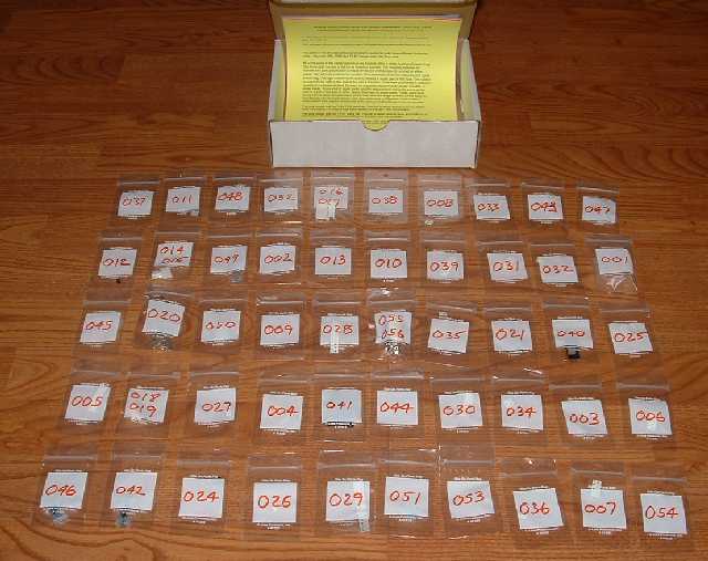 |
| The Parts Box | Box Contents | Parade of Small Bags |
The complete parts box is on the left. The contents, shown in the middle, are all of the small bags, which are placed in a larger zip bag. The tables from the spreadsheet are printed on colored paper for easy identification. There turned out to be exactly 50 small parts bags per box. They are laid out in the right picture. A bag might have a single component, or as many as 30. The VNA itself, and the T1-6T bridge are assembled from approximately 200 components. By number, most are 2 lead capacitors or resistors. There are a handful of integrated circuits, with 8 to 28 leads.
 |
 |
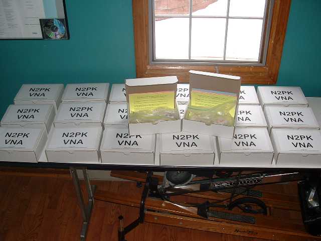
| Assembly Line | Goodbye Greg, Hello Harold and Bill |
All of the bags and boxes were assembled with an assembly line approach, and the left picture shows all 20 boxes on a table. Finally, groups of 6 and 7 boxes were combined and shipped out.
After the group purchase, I had 5 extra boxes, which quickly found good homes. The existence of a number of interested folks suggested that another group purchase would make sense. Plans are taking shape for that purchase. If you are interested, please follow this link, read about the new group, and send me email.
Back to my Experimentation Page