 |
| Board in the Box |
Greg Ordy
A version of the T1-6T bridge printed circuit board was created which was intended to easily fit into the Hammond 1590A die-cast aluminum enclosure. That board is used in the March 2004 Group Build. I needed to build up two of the new boards with enclosures. I had already built a board/enclosure combination a few months earlier, and it was difficult not only because of how the previous board fit into the enclosure, but mainly because of the alignment issues in attempting to get three RF connectors mounted at the correct points on the enclosure to mate with the board.
This time around I wanted to do a better and faster job.
What turned out to make it all easy was taking the time up front to build a jig which let me precisely drill all of the holes for a single connector with the required spacing. The jig was moved around the enclosure for each of the three connector locations. This page describes the process I used.
Building the board was no problem, and the schematic and parts on the board have not changed from other board versions. This page is more about putting the completed board in an enclosure.
The enclosure has tapered sides. The board was sized to fit approximately half-way into the enclosure. Because a snug fit is desired, some filing of the board may be required. If anything, the board is slightly too big, not too small. I flied the top and bottom edges of the board so that it would drop into the box, and end up at the correct depth. It was also necessary to slightly round the corners of the board, so that the board would avoid the corner posts in the box. Here is a picture of a board in the box.
|
|
| Board in the Box |
I have been using N connectors on the VNA and bridge. Due to the size of the bridge, I prefer the small flange male and female connectors. The small flange parts have a 0.7 inch by 0.7 inch footprint, whereas the full-size connectors require a 1 inch by 1 inch area. The female and male connectors have the same mounting dimensions; they mount in the same set of holes.
For each connector, there are four mounting holes, spaced 0.5 inches apart, on the corners of a square. The center pin hole is located in the center of the square. The holes are sized for 4X40 hardware. The first requirement is that the center axis of the three connectors be located on the same plane, so that the center pin can lie flat along the top of the board. It would also be nice if that plane was parallel to the top of the enclosure, so that the board was squared up in the enclosure. The translation of this requirement is that the connectors should be the same distance from the top edge of the enclosure.
In order to get the same spacing to the top of the enclosure, I decided to make a drilling jig out of a section of aluminum L stock. The enclosure could be placed in the corner of the L, so that the holes in the jig were a constant distance from top of the enclosure. Here is a picture of the jig, showing the pilot holes, spaced to match the holes in the connector.
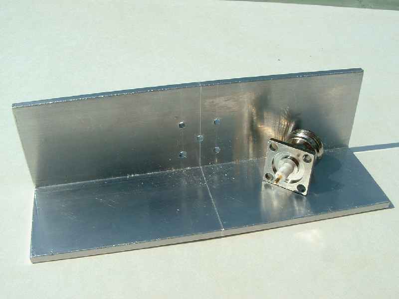 |
| Drilling Jig |
I scribed the center line of the connector around all sides of the L stock so that the connector could be registered against the box.
On one side of the enclosure, the female connector is located in the middle of the side. This is the device under test (DUT) connector. The other side of the enclosure has two male connectors, which mate with the VNA. These two connectors are spaced 2 inches apart, and are centered on the connector on the opposite side. The 2 inch spacing is important because it must match the spacing on the VNA, so that the bridge mates with the VNA.
The center line of the jig was aligned with the location marks on the enclosure, and then held in place with a clamp. Here is a picture of an enclosure clamped to the jig, ready to drill the DUT connector mounting holes.
 |
| Jig Clamped to Enclosure |
After all of the holes were drilled, the mounting holes were tapped for 4X40 hardware.
 |
| Tapping Holes |
After all of the holes were finished, I soldered brass finger stock to the bottom of the board. This was intended to make a good ground connection between the board and the enclosure. Here is a picture of the board soldered in place in the enclosure.
 |
| Completed Bridge |
Finally, here is a picture of the completed bridge on top of a VNA.
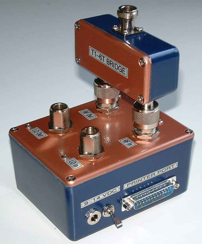 |
| Bridge on VNA |
The updated board works well with the enclosure. After I made up the drilling jig, getting the mounting holes in the right places became easy.
Back to my March 2004 Group Build Page
Back to my Experimentation Page