 |
| Initial Dummy Load Schematic |
Greg Ordy
I woke up feeling cheap one day. I needed a dummy load for my QRP transmitter, and I just couldn't handle the notion of spending money for it. I keep telling myself that the reason I keep all of the old parts (junk box) around is so that I can build things on a moment's notice, and at very little cost. Usually, there is some aspect of a project which requires buying something new. Maybe just one little part. For once, I was determined to spend nothing on this project, and just use up whatever I had lying around.
Perhaps a little background is in order. I had recently assembled a Small Wonder Labs DSW-II 40 meter QRP radio. With a 12 volt power supply, the maximum transmitter output power was measured at approximately 3.5 watts. The absolute maximum output power is 5 watts, with a slightly higher (13.8 VDC) supply voltage. I've been keeping this tiny radio on my desk. I unplug the coaxial cable from the #1 antenna port on my ICOM 756PRO and plug it into the DSW-II when I want to put it on the air using my vertical array.
I had also picked up a Mini Paddle keyer which nicely attaches to the side of the QRP radio box with magnets. The paddles are very small (compared to my Bencher paddles), and I like to practice using them to keep my transmitting error rate down. For practicing with the paddles connected to the QRP radio, I needed a QRP dummy load. I had been using the dummy load inside an old MFJ tuner, but the tuner cabinet was taking up too much valuable desk space, and it was overkill for this low power application.
I remembered having a bag of assorted carbon composition resistors in the junk box. The largest looked to be 2 watt units. I hoped that some exotic combination of parallel and series resistor networks would provide me with a 5 watt power level and a 50 Ohm impedance. This would also be a good exercise to review Ohm's Law, and make sure that I hadn't forgotten how to analyze simple resistor networks.
At around the same time, I was also starting to get some experience with the N2PK VNA which I had recently assembled. It is capable of making very accurate impedance measurements. I thought that it would be a good test case to sweep the dummy load from 1 through 54 MHz, and see how it performed as a function of frequency. Ideally, a (50 Ohm) dummy load presents a 50 Ohm resistance with no reactance at all design frequencies. In practice, they are never perfect. Close perhaps, but not perfect. Usually, the variations in impedance are small, and most of us lack test equipment with sufficient resolution and accuracy to measure small changes in load impedance. The N2PK VNA should be able to track fractional Ohm changes, and present a good picture of the actual load, as a function of frequency.
I emptied my bag of carbon composition resistors onto the desk. The size of the resistor indicates its power handling rating. The resistors in the bag were mainly the classic 1/2 watt resistor, although there were a number of 1 and 2 watt parts. I reserved the 1 and 2 watt parts, and put the rest back into the bag. I was looking for resistors in the range of 50 to 300 Ohms. This range was picked because it's relatively easy to create series and parallel combinations which result in a combined resistance of 50 Ohms, or at least near 50 Ohms.
Sadly, most of the 2 watt resistors I found had very high values, such as 3300 Ohms. I found two, 2 watt resistors that measured approximately 265 Ohms. Their parallel combination would create a 132 Ohm equivalent resistance. If there were three of those legs present, connected in parallel, the resulting resistance would be 44 Ohms. A little low compared to 50 Ohms, but not that far away. In order to increase the final resistance, the two mystery legs should have a resistance value around 150 Ohms, perhaps a little more. This is not hard to estimate, since three, 150 Ohm resistors in parallel will create a 50 Ohm equivalent result. I already had a 132 Ohm leg, so the other two need to be a little more than 150 Ohms to end up with something near 50 Ohms. This is obviously a shoot from the hip design process, but I was trying to figure out what resistor values could be pulled off to the side for a closer look. The selection of the two, 2 watt resistors started to suggest other values needed to arrive at the desired result.
The next interesting 2 watt resistor I found was 77 Ohms. This exhausted my supply of 2 watt resistors that had relatively low resistance values. [why are bags of assorted resistors never really that assorted?]
I found three, 48 Ohm, 1 watt resistors. Those three in series would create a 144 Ohm equivalent resistance, which is very close to my target of 150 Ohms. I then found a 106 Ohm, 1 watt resistor which could be combined with the 2 watt, 77 Ohm resistor, for a 183 Ohm equivalent. 183 Ohms is above the 150 Ohms target, but that seemed to err in the right direction, since the other two legs were under 150 Ohms. Here is a schematic of the putative dummy load based upon the resistors culled from the bag. The resistor values on the schematic are the measured values.
|
|
| Initial Dummy Load Schematic |
The question becomes, what is the net resistance of the dummy load at the input terminals? In order to compute that, it's time to drag out the formulas. Here are the relevant formulas for working with this dummy load.
| Common Electrical Equations Used in this Dummy Load | ||
| Equation |
Name |
Meaning |
|
|
EQ1 | Ohm's Law written to solve for voltage when I and R are known. |
| EQ2 | Ohm's Law written to solve for current when V and R are known. | |
| EQ3 | Ohm's Law written to solve for resistance when V and I are known. | |
| EQ4 | Equivalent resistance of resistors connected in series. | |
 |
EQ5 | Equivalent resistance of resistors connected in parallel. |
| EQ6 | Power, in terms of V and I. | |
 |
EQ7 | Power, in terms of V and R. |
| EQ8 | Power, in terms of I and R. | |
The first three equations are the permutations of Ohm's Law, which relates voltage, current, and resistance. In my mind, which can be a scary place, I like to think that what these equations tell me is that if I know two of the three terms, I can solve for the third.
Equations 4 and 5 tell us how to combine resistors in series and parallel, and compute the effective resistance of the group. In other words, how to combine several resistors connected in a specific way as if it were a single resistor.
Equation 6 determines power, in watts, from volts and amps. Power is simply volts times amps (current). The power consumed by something is equal to the voltage across it, times the current through it.
The final two equations also compute power, but use information from Ohm's Law to express power in term of resistance and either voltage (EQ7) or current (EQ8). This is accomplished with simple algebraic substitution, from Ohm's Law into the power equation.
Now we have enough tools to let us analyze the dummy load design. In the above schematic, I chose to organize the resistors so that the series and parallel combinations involved were as visible as possible in the drawing. Each leg (Leg 1 to Leg 4) is either a single resistor, or a series combination of resistors. EQ4 tells us how to combine resistors in series. Of course Legs 1 and 2 are trivial, since a single resistor is equal to a single resistor. Once the Legs are reduced to single equivalent resistances, it becomes possible to use EQ5 to combine the four legs in parallel, and create a single equivalent resistance. This is the resistance of the dummy load. We've combined seven individual resistors down into one equivalent resistor.
Here is a second view of the schematic with the equivalent series resistances of the legs off to the right of the leg, and then the parallel combination of the legs at the bottom.
 |
| Schematic with Net Resistance Calculations |
Leg 1, for example, being a single resistor, has a leg resistance of 265 Ohms. The quantity 0.00377 is the reciprocal of 265, which is used in EQ5. Legs 3 and 4 have series combinations of resistors, and their values simply add together (EQ4) to form the net leg resistance. 145.4 Ohms and 183.5 Ohms, respectively.
I added up the reciprocals, and then took the reciprocal of that sum to apply EQ5, since the 4 legs are in parallel. The result was 50.28 Ohms.
Now when I first did this calculation on paper, my jaw just about hit the floor. What were the chances that this casual combination of seven resistors would end up with a net resistance of 50.28 Ohms, very close to the target of 50 Ohms? I took that as a sign that I really should build the dummy load. It was fate that I met those seven resistors. Perhaps I should have bought a lottery ticket on that day?
While the dummy load resistance is nearly perfect, a few more calculations are needed. Especially being a dummy load, designed to accept power and convert it to heat, it's necessary to do a power calculation for each resistor, and make sure that the resistor is within its power rating, either 1 watt or 2 watts with the parts I was going to use. Here's where equations 6 through 8 come in handy. In addition to the resistance, we need to know either the voltage across the resistor, or, the current through the resistor. If we know one, we can calculate the other, and end up with the power dissipation in the particular resistor.
In this case, I decided that the maximum power that I would ever pump into the dummy load was 5 watts - the limit of the QRP transmitter. I had two quantities, 5 watts and 50.28 Ohms. Using EQ7, I could solve for the voltage at the input to the dummy load. It is the square root of the quantity power times the resistance, which is, 15.86 volts. This means that 15.86 volts will be across all 4 legs when 5 watts are delivered to the dummy load. Calculating the power in R1 and R2 is now trivial, using EQ7 again. The power, in watts, is the voltage squared, divided by the resistance. I can also compute the current going through the resistor, since I know the voltage across the resistor and the resistance. Here is the final drawing of the schematic, this time with current, voltage, and power values added for each resistor.
 |
| Schematic, with Voltage, Current, and Power Indicated (5 Watts input) |
Because each leg is a series combination of resistors, the current will be the same for all resistors in the leg. Where else would the current go, but from series resistor to the next series resistor? Since I already know the resistance for each leg, I can compute the leg current by dividing the voltage across the leg (15.86 for all legs), by the leg resistance. The leg currents are shown in units of milliamps, in blue, to the left of the schematic.
The voltage across each resistor will be the leg current times the resistance, simple Ohm's Law. The power consumed by each resistor will be the voltage across the resistor times the current going through the resistor. The voltage and power are shown in red text, under each resistor.
The goal now is to compare each power rating against the expected power consumed. Most of the resistors are being asked to dissipate around 50% of their rated power capacity. No sweat. The worst case is R7, the 106.5 Ohm resistor in the lower right corner. It is a 1 watt part which will dissipate 0.79 watts which is 79% of it's capacity. If ever this dummy load burns out, it is probably a good guess that R7 was the first to go. A math consistency check can be performed by adding up the seven power values, and double checking that the sum is 5 watts, the given input power.
A final comment on power rating. The resistor power ratings are based upon a 100% duty cycle. There are several factors that can change the rating. If the resistor heat is removed, by a heat sink or fan, for example, the power rating will increase. Another way to effectively increase the power rating is to decrease the duty cycle. A figure often quoted for the CW duty cycle is 50%, and 33% for SSB. If you know something about the signal sent into the dummy load, such as its duty cycle, you can exploit that information to increase the power rating. Be careful when heating carbon composition resistors. They can change value in response to excessive power dissipation, and their value will be changed permanently.
While digging through the junk box, I found a small aluminum enclosure which had a BNC connector on one end, and an F-59 connector on the other end. The case held a small transformer which was used for a short amount of time many years ago, and was no longer needed. The BNC connector was exactly what I was looking for, matching the BNC connector on the QRP radio. Here is a picture of the open box and the seven selected resistors. Please click on the picture for a larger view.
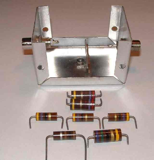 |
| Dummy Load Parts |
I used a two-part epoxy to glue each resistor to the inside of the enclosure top. This is often called dead bug construction, since the part is on it's back with the legs pointing straight up. The resistors were arranged to group all of the RF input leads together, and all of the ground leads together. This simplified wiring the parts together. I soldered the series resistor combinations before gluing them into the case. I mounted a three-lug terminal strip at the center of the top, using a hole that was already in the case from the previous application. In wiring up the dummy load, I only used the center ground lug. At some future point I could add a diode and capacitor on the other lugs, creating the typical RF detector circuit, which could be routed out of the box on the F-59 connector.
The power rating of most parts can be increased if the part has a heat sink. I don't believe that garden-variety epoxy is a very good thermal conductor, but the resistors are in contact with the top of the box, and any generated heat would tend to be conducted onto the top. While this is not the best heat sink, it is probably better than nothing, and will increase the power rating of each resistor.
It's a good idea to minimize lead length. As the frequency rises, wires exhibit more and more inductive reactance. This reactance is not desired in a dummy load. I simply located the parts in the most reasonable locations, and wired the resistor legs together with hookup wire.
Here is a picture of the box internals after assembly.
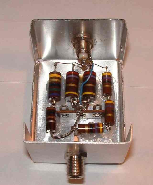 |
| Assembled Dummy Load |
Once the dummy load was assembled, I used a DVM to measure its resistance. The DC resistance was measured at 50.3 Ohms. This is very close to the computed 50.28 Ohm value. Since I used the same meter for all initial individual resistor measurements, however, that really doesn't prove too much. The meter is probably better at making relative measurements as opposed to absolute measurements. In other words, if two example resistors measure as 100 and 120 Ohms, even an inexpensive meter should measure their series combination as 220 Ohms. The true resistance may not be close to 220 Ohms. It is worth it to verify the result, however, to check for assembly errors, or check for the destruction of parts due to excessive soldering heat during assembly.
What is more interesting is the performance of the dummy load at radio frequencies. After all, that's where it will be used. A RF check will uncover a whole range of flaws. The usual problem with homebrew dummy loads is the accidental use of wire-wound resistors which act as inductors at RF. This mistake will render a dummy load useless, not just a little off. That mistake will not show up with a DC resistance check, but it will show up with an RF check.
Now the fun begins. I powered up the N2PK VNA and programmed a sweep from 1 MHz to 54 MHz with 1 MHz spacing. I captured the SWR, as well as resistance and reactance. Here is the SWR graph.
 |
| Dummy Load SWR versus Frequency |
The VNA-measured dummy load impedance at 1 MHz was 49.99 - j 0.06 Ohms. The resulting SWR was very near unity. The computed value was 1.0012, but the accuracy of the measurement probably does not support that many significant digits. In any case, the dummy load has an SWR of 1.0 at 1 MHz. As the frequency was increased, the SWR also increased, following a nearly linear curve. At the upper frequency of 54 MHz, the SWR rose to approximately 1.07. In the big picture scheme of things, this is a very modest increase, and is usually undetectable with most test equipment.
 |
| Dummy Load Resistance versus Frequency |
This graph plots the dummy load resistance as a function of frequency. While it begins at 49.99 Ohms at 1 MHz, it drops to 48.92 Ohms at 54 MHz.
 |
| Dummy Load Reactance versus Frequency |
Although I began with a guess that the dummy load might become inductive as the frequency increased, it actually became capacitive, exhibiting -2.6 Ohms of reactance at 54 MHz. My inductance estimate was based upon the effect of the lead length between resistors. In reading several web pages which discussed resistors, there was general agreement that carbon composition resistors exhibit capacitive reactance as the frequency rises. This capacitance apparently is large enough to negate the lead inductance, and create a net capacitive result. Whatever the reason, I have what I have.
The resistance and reactance graphs include a purple trace named Standard. These are the traces of my 50 Ohm calibration standard, made after the dummy load measurement. This additional measurement was designed to verify that the VNA had not lost calibration. Since the variation in resistance and reactance is small, it is a good idea to ask if the change being observed is truly due to the dummy load, or some other test fixture errors. If there was any error, it would be due to the male to male BNC adapter which is used to connect the dummy load to the VNA. This adapter is not part of the calibration setup, and lies beyond the reference plane. In order to investigate this potential error, I selected a normal 50 Ohm BNC dummy load (low power), and connected it to the VNA with two different configurations. One made a direct connection to the VNA base N connector, and the other was through a male to male and female to female BNC adapter (on top of the N connector). This was an over exaggeration of the BNC plumbing between the VNA and the dummy load. The resistance and reactance differences between these two configurations was measured. The resistance difference was 0.12 Ohms (maximum). The reactance difference was 0.8 Ohms (maximum). Since the additional interconnection length was doubled over the dummy load lash up, these differences should represent a worse-case effect, perhaps by a factor of two.
Even if the worst-case uncertainty is assumed, the general trend of the dummy load measurement is not substantially altered from the graphs shown.
If nothing else, I did find everything I needed in my junk box. The final result is a usable dummy load for my 40 meter QRP radio. Since I was rather casual in my construction technique, I was relieved to see that the dummy load offered very good performance up through the 6 meter band.
Back to my Experimentation Page