 |
| RF Current Probe Schematic |
Greg Ordy
If you want to be confident that your multi-element vertical array is operating as designed, it is essential that you measure the RF current magnitude and phase at each antenna element feed point. Simultaneous measurement of two elements using a dual-trace oscilloscope is particularly valuable because the magnitude and phase of each element is displayed. In the case of phased vertical arrays, what matters is the relative relationship between element current magnitude and phase, not their absolute values. Current magnitude is compared between pairs of elements. Likewise, current phase is also compared between pairs of elements. The oscilloscope is a very good tool for this job. If you do not measure and verify the current relationships you expect, you will not obtain the performance you expect. This is especially critical for optimizing the F/B (front to back) ratio of the array, which is very sensitive to current and phase ratios (as opposed to gain, which is far less sensitive).
This page describes a very simple RF current probe which can be built for no more than a few dollars. Combined with a dual-trace oscilloscope and a suitable RF generator, relative current measurements can be easily made.
The intended frequency range for this probe is from 0.5 MHz through 10 MHz.
For use with a dual-trace oscilloscope, you will need at least a pair of probes. In my case, I was working on a 6-element array, so I built six. Since the probe is inexpensive, I would suggest building one for each element, even if you have more than two elements. Switching probes from element to element takes time better spent making measurements. It's easier to switch cables right at the oscilloscope. Of course a coaxial cable will be required for each probe as well.
This is the first of two pages on the subject of RF current probes. The second was added in June of 2007, and can be found at this link.
The design presented here is not original. A number of sources describe what is essentially the same design and measurement technique. The heart of the current probe is a small ferrite core which is wound with approximately 10 turns of solid hookup wire. A wire (the antenna!) carrying the RF current is passed through the center of the core. The RF current passing through the core induces a voltage in the winding. This voltage is carried back to the oscilloscope through a coaxial cable. At the scope, the coaxial cable is terminated with its characteristic impedance, 50 ohms, for example. The voltage across the resistor is measured by the oscilloscope. The trace shown on the oscilloscope reflects the RF current magnitude and phase.
Page 8-27 of the 18th Edition ARRL Antenna Book, page 11-24 of the 3rd Edition ON4UN book, and page 50 of the May, 1984 issue of Ham Radio all describe this type of design. The May, 1984 Ham Radio reference is part 6 of the series on phased vertical arrays by Forrest Gehrke, K2BT (available from the ARRL on CD-ROM).
The designs do not agree on whether or not the pickup itself should include a termination resistor. It seems that all agree that a termination resistor is required at the oscilloscope. My first set of probes did not include a resistor at the pickup torroid. Upon further reflection, however, I decided that the pickup-side resistor could not hurt, and might indeed help. It would help by ensuring that the transmission line back to the oscilloscope is run flat, and sees its resistive impedance on both ends. When a transmission line is not terminated in its characteristic impedance, it will act as an impedance transformer, and that's the last additional factor we need in this situation.
In my case, I used type 75 ferrite material. The actual core is an Amidon type FT50-75. This number signifies a 1/2 inch OD core made of type 75 material (particular ferrite mix). The core provides good results from 0.5 MHz through 20 MHz. Please consult the Amidon web site for more information. Other mixes, such as type 43 and type 72 will also work.
Here is the schematic of the probe.
|
|
| RF Current Probe Schematic |
In the schematic, the coaxial cable and the termination resistors are all shown as being 50 ohms. Other values may be used (75 ohms for example), so long as you terminate the cable with a resistor matching its characteristic impedance.
Here are top (or front) and bottom (or back) pictures of the current probe. Please click on a picture for a larger view.
 |
 |
 |
| Front View | Back View | Core Close-up |
The probes are constructed on pieces of perfboard, approximately 3 inches tall by 1.25 inches wide. For added support, two layers of perfboard were glued on top of each other, so that the holes through the boards lined up. The ferrite core is wound with 10 turns of a small gauge solid hookup wire. The core is positioned vertically on the board, and the two wires pass through holes in the boards to the back of the board.
A 3 inch length of #14 stranded wire is passed through the center of the core. Each end is terminated in a 1/4 inch ring terminal. My particular antenna elements connect via 1/4 inch studs, so this was the appropriate style and size. Your application may differ. A close-up of the core is shown in the right picture.
A chassis-mount coax connector (SO-239) is mounted in a hole on the opposite of the board from the core. The connector is the type where a nut threads on the shaft of the connector. I found that it was impossible to mount the connector through two layers of perfboard, as they were too thick. The nut could not thread onto the connector. So, I made the hole on one of the two boards large enough so that the nut only tightened on one board.
The two wires from the core are connected to the coax connector. The connections were coated with a product called Liquid Electrical Tape, which provides insulation and corrosion protection. The pictures shown above were taken before I modified my probes to include a 50 ohm resistor across the coax connector. I simply removed the coating, soldered on a resistor, and reapplied the coating. The resistor is discussed in the previous section.
After construction, a liberal amount of two-part epoxy was used to glue the boards together, protect the wire leads, affix the core to the board, and to force the center wire to go through the core centered and perpendicular to the plane of the core. Several applications of epoxy may be needed to completely coat the core and the wire in the area around the core.
Since we will be making relative measurements, one procedure you will not hear about on this web page is calibration. But, what matters in this case is symmetry. Each probe must be built exactly like all of its peers. The following points of symmetry should be observed.
Make sure all of the cores are from the same ferrite mix, and are of the same size.
Make sure that the same number of turns are used on each core. Use the same wire for all cores. Wind the cores with closely-spaced turns that should take up the same angular percentage of the core. I use a telephone hookup wire.
Observe the winding direction around the core, and make sure that the same wire is connected to the center pin of the connector for each probe.
Dress the core wires in a similar manner on each probe. Use epoxy to affix them to the same place on each probe.
Center the pickup wire in the code, and make sure that it goes through the core perpendicular to the plane of the core. Use enough epoxy so that the wire cannot bend in the immediate (1 inch) vicinity of the core.
Make sure that identical lengths of coax are used to connect the probes to the oscilloscope. Of course what matters is electrical length, not physical length. If you cannot verify that the lengths of cable are electrically identical, then cut identical physical lengths of cable from the same roll. For typical (0.66% velocity factor) coax, at 3.8 MHz, 1 foot of cable is approximately 2 electrical degrees long. Since the cables must be long enough to get from all of the elements to the oscilloscope, they will usually be at least 25 feet long (highly dependent upon the array spacing and configuration). It's very easy to introduce several degrees of phase error with just differences in the cables.
To test the symmetry of your probes and cables, connect the probes in series to the same element. The two traces on the oscilloscope should exactly overlap, both in magnitude and phase. If you note a small phase error, you can correct it by adjusting the length of a cable [the Ham Radio article suggests placing a 5 - 25 pf trimmer across the core which lags in phase and adjusting it to remove the phase difference]. If you do no have identical magnitudes, then the cores must differ in their windings. It is also possible that your oscilloscope is not symmetric between channels. You can reverse the probes to investigate the symmetry.
[NOTE: do not operate the probes without having the termination resistors in place. Without them, voltages at the input to the oscilloscope may rise to high levels (depending upon the power level feeding the antenna). These high voltages could harm you, or your oscilloscope.]
 |
 |
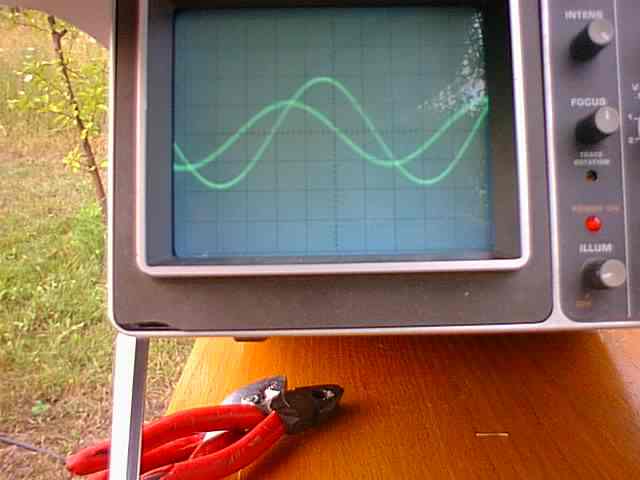 |
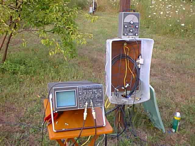
| RF Probe on Antenna | Oscilloscope Setup | The End Result |
The left picture shows the current probe connected to an antenna. The probe is connected in series with the feed wire. I selected the size of the perfboard so that the coax connector would be brought off to the side of the 2 inch diameter antenna element.
The middle picture shows the oscilloscope setup, near the center of the array. You can see the two coax cables from two probes connected to the front of the oscilloscope. I used a BNC T connector to allow me to connect a 50 ohm termination resistor across (in parallel with) the cable. As the note above cautions, be sure to connect the termination resistors. Note the Yellow Jacket spray on the ground. An essential part of antenna work in Ohio in the summer.
The right picture shows a pair of traces on the oscilloscope. The picture came from a pair of elements in my 80 meter array. By adjusting the oscilloscope settings, magnitude and phase can be measured.
I found that the signal level provided by an impedance analyzer, such as the MFJ-259 was adequate to indirectly drive the oscilloscope input by directly driving the array. The oscilloscope sensitivity was near the top of its range, however. I suspect that I will be looking to pick up a stable RF generator that produces a stronger signal. A possibility is to run my ICOM 706MKIIG at the lowest power setting, which will probably provide more than enough signal back at the oscilloscope.
If you are building a phased vertical array, current probes like these, along with a signal generator and a dual-trace oscilloscope will let you verify the current magnitude and phase relationships between the elements. This is a good way to get the most performance out of your antenna system.
In June, 2007, a second page was written on the subject of RF current probes.
Back to my Experimentation Page