 |
 |
| My First SoundBlaster Interface | ACC1 (8-Pin DIN) Cable |
Greg Ordy
The product name SoundBlaster™ has become synonymous with computer audio card (or sound card). If the audio output and input of a radio (Amateur Radio transceiver in this context) are connected to the card, the computer is now in a position to process the received radio audio, and generate audio for the transmitter. The potential applications are almost limitless. In recent years, a number of digital modes based around a software implementation on the computer have become quite popular. These include PSK-31 and MFSK16. A computer interfaced to a radio can also implement most all of the older modes, such as SSTV, RTTY, and even CW. Fortunately, many of the popular software packages needed to complete the picture are either free, or very low in cost. The last missing piece is the interface between the radio and the computer. Generically, the term SoundBlaster Interface is often used. My version of the interface has been directed towards ICOM radios, especially those with the 8-pin DIN jack which is usually called the ACC1 accessory jack. I know that this particular interface will work with most of the recent-vintage ICOM radios, but be sure to check your particular radio before plugging in the soldering iron.
There is nothing too exciting about my circuit or implementation. Perhaps a few ideas will emerge from this page, and can be of use in your own interface. This SoundBlaster Interface can work in conjuction with the CI-V Computer Control Interface that I use. The push to talk (PTT) signal from the CI-V interface is fed into the SoundBlaster Interface in order to place the radio into the transmit mode.
A wealth of information exists on the Internet concerning SoundBlaster Interfaces for Amateur Radio applications. Here are some of my favorites.
BUXCOMM, JAMECO, MFJ, RIGBLASTER.
DIGIPAN
SSTV
DO TRADEMARKS, CREATEIVE LABS,,, SOUNDBLASTER, SOUND-SPACE-BLASTER
The interface is really very simple. There are three primary signal flows. The first is the audio from the receiver which is connected to the Line-In of the audio card. The second is the Line-Out of the audio card which is connected to the radio transmitter audio input. The last flow is the push to talk (PTT) control signal which places the transceiver into the transmit mode.
As might be expected, there are details, and even issues.
In the simplest form, the audio connections can be made with nothing more than cables. For this to be the case, however, at least two things need to be true. The signal levels at the outputs and inputs must be compatible, and there must not be any hum caused by a ground loop. The only way to understand the signal level issue is to study the interface specifications of the radio and/or the computer. Since this information might not be readily available, you may be forced to experiment. The ground loop problem is a simple yes or no question - either you have one or you don't. Fortunately, the solution for the ground loop problem is simple. An audio isolation transformer will transfer the signal but break the direct ground connection between the computer and the radio (at the audio connection point). You need to be a little careful when using an isolation transformer because once you cross over to the other side, you have to make sure that the audio ground connections do not come into electrical contact between the pieces of equipment.
The push to talk (PTT) signal is part of the radio, but is actually not part of the audio card on the computer. After all, the audio card is about audio, not control signals. The common way to control the transmitter in the radio is via a modem control line on one of the computer serial ports (RS-232). These are lines that the computer uses to communicate with an external modem. While external modems have gone the way of the buffalo (not used much any more), the control signals are still available on the serial port, and most all software that needs to turn on a transmitter will have some provision to do so via a modem control line (this is usually an option buried in the program).
Sadly, the PTT connection has become much more complicated because of two issues. First, personal computers once were typically equipped with two external serial ports. In recent years, most computers come with a single external port. This means that if you have more than one serial device, you will have to swap cables from time to time. I hate swapping cables. There are other alternatives. You can purchase boards that plug into the computer that provide additional serial ports. I have a card with 4 additional serial ports since I seem to have all sorts of gadgets that use a serial interface. It is also possible to purchase serial ports which connect to the computer via the USB port, which has become quite popular and standard in recent years.
The second issue related to PTT lines is the fact that a serial port can only be used by a single software program at one time. This is a restriction imposed by most all operating systems, and is actually quite reasonable if you stop and think about (which I won't do here). In the typical amateur radio station which includes a computer, one of the primary programs is a logging program, which records contacts and other information. One of the great features of logging programs is that they ask the radio for information such as the frequency and mode of the radio. You don't type it in manually, the computer asks for it from the radio. With no exceptions that I am aware of, this interface is also made over a serial port. Please remember that this interface I am talking about now has nothing to do with audio. This is a digital data interface that goes between the computer and the radio, over a serial port, for the purposes of reading and controlling the state of the radio from the computer.
Here's the problem. You sit down in front of your equipment, turn on the radio, and fire up the logging program. How many of us do that? The logging program opens the serial port to the radio so that it can interact with it. At this point, you would like to use a second program to make a PSK-31 contact. For that program to turn on your transmitter, it needs a control line which is located on the serial port that is now consumed by the logging program. With a single external serial port, you are stuck. You can't do both at once. And, when you want to switch software, you have to swap cables. This is conceptually very sad because the logging program usually never cares about the modem control lines, it only wants to send and receive data. The other programs that simply want to turn on the transmitter only need the modem control lines, and don't care about the data signals. They really could work over the same serial port, but the functionality is all lumped together in a single port, and only a single program at a time can access a single serial port.
So, the usual solution is to use more than one serial port. On one port you will use the data lines to send and receive control commands to and from the radio. On the other port you will only use the modem control lines (well, one line) to turn on the transmitter.
Another solution is to use a single program that integrates both logging and digital mode (via the audio card) functions. These are becoming quite common. There are many good reasons for integrating different software functions into a single program. One happens to be that they can then all share the single serial port, and you can do everything you need with only one port.
Most all SoundBlaster Interfaces, including this one, will have an input signal named PTT or possibly Send. This is the signal from the computer that puts the radio into transmit mode. The signal could be either an RS-232 level signal (+/- 12 VDC) or some other electrical interface such as a line that floats high, and is pulled to ground to indicate transmit. In this design, my PTT signal directly drives the radio PTT signal. This works because the modem control signal, which is an RS-232 level signal, is converted to the appropriate level in my homebrew CI-V Interface, described on another page. In other words, I obtain the PTT signal for the SoundBlaster Interface from my CI-V Interface, which is connected to a serial port. For my applications, radios, and operation style, this all works fine. Your situation might be quite different. I have included a capability to drive the PTT input for this SoundBlaster Interface directly from an RS-232-level signal. Through a simple cable and connector you can grab the PTT signal from an unused serial port without going through the CI-V Interface.
Three more comments about the PTT line before returning back to the audio signal flow. Many of the SoundBlaster Interface designs use an optocoupler in the PTT signal path. The idea is to provide complete isolation between the computer and the radio. My experience has been that an optocoupler is not needed. I don't think it can hurt the situation, but it has never been necessary in my limited experience. The second comment I would like to make is that I have found it desirable to be able to break the PTT connection with a switch. This is because it is common that the unused state of the modem control signal on the serial port turns on the transmitter. Once you get into the application program, it will correctly control the transmitter. But, when you are not in the program, the transmitter will turn on. This is a bad situation. With the switch on my interface, I first get into the program, then I switch the interface into the SoundBlaster mode, and I'm all set. When I'm done with the program, I turn off the interface, then turn off the program.
And finally, with respect to the PTT line, in some cases, the line is not even needed at all! This can happen when you use VOX on your radio to automatically enter transmit when the audio card produces a signal. This may not be possible unless you enter the radio via the microphone jack. For example, I enter the radio via the modulator input on the ACC1 jack. This signal does not trigger the VOX. Only the front panel microphone signal will trigger the VOX. Of course I like to keep a microphone plugged into that jack, so I prefer to use the ACC1 jack. A clever variation on the VOX idea is to put the VOX into the interface. This appears to be exactly what the SignaLink product does. They sample the transmit audio and generate the PTT signal automatically from it. In fact, they claim a trademark on the term Auto-PTT™, which is rather self-explanatory. With their system, or any design that would derive the PTT signal from the audio going into the radio transmitter, you do not need to obtain a PTT signal from the computer. This can potentially reclaim a serial port, which is a precious resource on the computer. The only down side I can think of to this approach is that the timing of the Auto-PTT signal must not cause problems with the data transfers. In other words, the transmitter must turn one before data arrives, and the hang time must not be so long that you miss the first part of the message coming back from the other station. I assume that their design has controls to adjust the timing. I don't know enough about the vaious digital modes to know how critical the timing is, and if this approach has any other problems. On paper, however, it is very attractive, and seems like a good idea.
While I don't believe that an optoisolated PTT signal is needed, I can't say the same about audio isolation transformers. Without them, I have always had ground loops. You will know a groud loop when you hear one, it is a nasty low frequency (60 Hz) signal that tends to dominate the overall audio signal. Isolation transformers have always solved ground loop problems for my situations.
In addition to the isolation issue, it is necessary to consider the signal level issue. On the ICOM radios that I have worked with, the ACC1 accessory jack contains an audio signal which is low level, and independent of the audio volume knob. This is a great situation for digital modes since you can present the computer with a fixed audio level, and if you want to turn down the speaker volume you can do so. It has also been my experience that this level is directly compatible with the Line-In levels of computer audio cards. The interface does no more than take the audio from the radio accessory jack, put it through an isolation transformer, and then send it to the computer. Further gain adjustment will be available on the computer, through the software mixer application.
Audio transformers commonly used in this application seem to come in one of two different impedance pairs. One has a 600 Ohm primary and a 600 Ohm secondary. The other has a 1000 Ohm primary and an 8 Ohm secondary. The terms primary and secondary aren't important in this application, and the transformer can be driven in either direction. For the ICOM radios via their ACC1 accessory jack, the 600 Ohm to 600 Ohm transformers are used. The 8 Ohm transformer is used when you need to obtain your radio audio from a speaker output. Speakers outputs usually drive 8 Ohm loads. In this case, you will also need to add a resistor-based level control so that the very strong signal at the speaker jack can be cut down to the Line-In level of the computer audio card. If you don't reduce the signal, you will probably overdrive the computer input, and end up with nothing but distortion. If at all possible, avoid using the speaker output of your radio as the signal source for the computer. Fortunately, the ICOM radios I have been using all have an alternate audio output signal.
The other direction, from the computer Line-Out to the radio transmitter, is a similar story. I have found that the 600 Ohm/600 Ohm transformers work well and provide isolation. In this case, however, I add a variable attenuator control (potentiometer) to the output of the transformer, before entering the radio. I do this to provide a fine degree of adjustment to avoid overdriving the radio transmitter. You will have some degree of control on the Line-Out level via the computer mixer software, but this can be too coarse. With a variable control, you can be sure that your transmitter is driven with the optimum input level. Especially with the digital modes of communication, transmitter distortion should be avoided.
Now a word on the topic of convenience. I dislike having to swap cables, especially on a frequent basis. When considering your proposed station wiring, ask yourself if you will need to swap cables to move between certain modes. For example if you decide to interface the radio via the speaker output and microphone jack, you will obviously need to swap cables when you want to go between the digital modes and good old SSB. If your radio has no other audio in/out capabilities, you really have no other choice. You could certainly build accessory switching boxes as an alternative to cable swapping. The interface described on this page connects to the rear panel of the radio, and at most, I have to flip a switch on the interface when I want to use digital modes based on the computer. Of course my microphone has an On/Off switch so that I can disable it when using digital modes via the computer. If you don't disconnect/disable your microphone, room noise might be transmitted at the same time as your signal.
Another good word to ponder is expandability. How easy is it to expand your interface if you decide to do something new and different with it. Here's an example. One of the pins on the ICOM ACC1 jack is the FSK RTTY keying signal. Let's say you wired up a cable to go to a SoundBlaster Interface, and at the time, you never thought that you would operate RTTY. So, you left that pin unconnected. Now, at some future point, you would like to explore RTTY. How do you get at that signal? Do you build a special RTTY interface, and swap cables when you want to run RTTY as opposed to PSK-31? Do you replace the cable in your existing interface, and add the extra signal? If so, what happens on the other end of the cable? One of the problems with acessory jacks is that they tend to aggregate many different signals. If you wire up a connector for it, will you ignore some signals? I find that difficult to do, since I always end up kicking myself because I don't have some signal available. In this design, I have tried to avoid this problem by bringing out all of the signals from the radio, and use what I need for the SoundBlaster Interface, as well as making them all available for some future interface.
Most computers have audio cards for the purpose of playing music and little beeps and sounds that are part of using the computer. When we use the card to drive the radio transmitter, that function is lost - at least for as long as we are using the radio application software. One solution to this problem is to install a second audio card into your computer. Since low-end audio (sound) cards are now available for very little cost (under $20 USD, 2002), it is an attractive addition. This further reduces the need to swap cables, and lets your normal computer audio function at the same time that you are doing audio processing with your radio. I do not yet have a second sound card in my computer yet, but I can tell that I am just about there. I'm sure that I will add one in the next few weeks.
SWITCHES IN COMMERCIAL UNITS SPEAKER OUT ON OLD CARDS, CABLE SWAPPING....
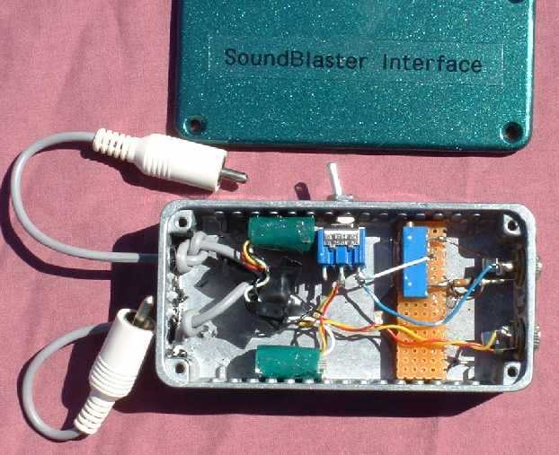
This page is about the second interface design that I have built. The first worked just fine, but in building it and using it, I learned all sorts of nuggets of knowledge that inspired me to iterate into a second version. The first version consisted of an audio interface box and a special cable. The following pictures show the box and the cable. Please click on a picture for a larger view.
|
|
| My First SoundBlaster Interface | ACC1 (8-Pin DIN) Cable |
The interface was constructed in a small aluminum box made by Hammond (LINK!). I have use this box in other projects. The aluminum is quite thick, and the box is nearly undestructable. The green items epoxied to the top and bottom sides of the box are Radio Shack (LINK!) 1:1 audio isolation transformers.
The computer is connected via the two 1/8" (3.5 mm) stereo jacks on the right side of the box. One jack is the Line-In signal, and the other is the Line-Out signal. The computer is a stereo device, whereas the radio is mono. By convention, the LEFTXXXX channel is used. The left channel is always the tip (as opposed to ring) signal on a stereo plug.
The Line-In signal to the computer is connected to the output of one of the isolation transformers. The input of the transformer comes from the fixed-level audio output of the radio. Initially, that connection was made through another 1/8" jack mounted to the left side of the box. My plan was that I would build the box with isolation transformers, but I would simply attach the jacks to the box and see if I had a ground loop problem. If I had a problem, I would switch to insulated (isolated) jacks. Since insulated jacks can be difficult to locate, I would only switch to them if I needed them.
Well, I did indeed have ground loops, and the nasty hum that goes with them. Then, I was unable to find insulated jacks locally, and I was too impatient to wait for a mail order. So, I simply replaced both jacks with short sections of cable that went directly from the isolation transformers to the outside world. In other words, the case was no longer a common ground. This solved the ground loop problem, but now I had short cables hanging out of the box. The cables can be seen on the left side of the box is the previous picture. They terminate in Phono (RCA) plugs.
The computer Line-Out signal (the left channel that is), enters the case on the right, then goes through a level adjusting variable resistor and a switch, which cuts off the computer audio from being sent to the radio. After the switch, the signal goes through the isolation transformer, and then out of the box on one of the Phono plug cables.
The variable resistor is a 10-turn 10K Ohm precision potentiometer that I happened to find in the junk box. I mounted it to a stack of perf board scraps, and located it so that a hole drilled in the side of the box could be used to adjust the control. I used epoxy to attach the perf board to the case, and the control to the perf board.
Except for the lesson of the ground loop, this design worked quite well. It was easy to adjust the level control so that the computer did not overdrive the radio.
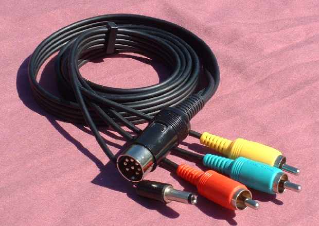
The connection to the computer was made with a pair of stereo cables with 1/8" plugs on each end. The remaining question was how to connect the two Phono plugs to the ICOM ACC1 jack?
Although the ACC1 jack has 8 signals, I decided at the time that I only cared about 5 of them - the audio in, audio out, PTT control, DC voltage, and ground. I wanted to use shieled cable as much as possible, in order to reduce the chance of hum and RF interference. The solution I decided to use was to adapt a 4 channel shielded audio cable with Phono plug ends. The cable is a Radio Shack item. As soon as I removed the cable from the plastic package, I cut it into two halves. Each had 4 Phono plugs on one end, and wire on the other. I connected the wires to a standard 8=pin DIN plug. This is the connector used for the ICOM ACC1 jack, and is another standard Radio Shack item.
Soldering all 4 shielded cables (signals and grounds) to the 8-pin plug was time-consuming, but successful. The custom cable is shown in the previous right picture. I did replace one of the Phono plugs with a 2.5 mm power connector. This was for the DC voltage signal. The three remaining Phono plugs were audio-in, audio-out, and PTT.
USE OF STEREO JACKS, WHAT SIDE TO USE. NOT EXPANDABLE, NOT ALL SIGNALS.
After my first implementation, and what I learned from it, I ended up with the following design.
BRING UP HOW CABLE CAN BE USED AGAIN WITH 706. FERRITE BEADS....
This page is currently under construction. Check back soon.
Back to my Experimentation Page