|
Components of the basic cylinder |
Greg Ordy
Using plastic pipe parts to built a feed point enclosure for a center-fed dipole is hardly unique or original. This web page looks at yet another variation on the old theme.
I was working on building parts for an 80 meter Moxon Rectangle. The overall antenna design is described on another page. The elements were made of wire, and the center feed point was the typical two wires coming to a single point where the feed line attaches design - a dipole. In this case, the feed point of each of the elements was slightly more complicated. I knew that I needed room for a current choke, in order to attempt to keep unbalanced current from flowing on the feed line, and disturbing the desired radiation pattern. In addition, I wanted to locate a DPDT relay at the feed point that could control the insertion of inductance for shifting the antenna resonance from the SSB (3.790 MHz) DX window to the CW (3.525 MHz) DX window. What I needed, therefore, was an enclosure to hold the current choke, the relay, and two powdered iron toroidal core inductors. In addition, the enclosure should be as light and small as possible, while providing enough strength to stand up against the tension of the wire elements and the feed line. Resistance from weather damage is also important.
I always seem to think about metal boxes before plastic. Three key issues to consider are the need for electrical shielding, box strength, and weatherproofing. Cost is also always an issue. I did realize one interesting key point which really made metal undesirable. For the current choke, I wanted to use a W2DU-style design, available from The Wireman (their product #833). This design consists of 50 ferrite beads over a length of thin but high quality and high power Teflon coax. One end of the Teflon coax (RG-303) connects to the female SO-239 panel connector, while the other end connects to the SSB/CW relay. After thinking about it for a bit, the light bulb went on. I realized that it defeats the entire purpose of the choke if you ground the two ends of the RG-303 together. The ferrite section is effectively shorted out. No wonder plastic pipe is often used to enclose chokes and baluns!
Since electrical shielding was not important for this application, and given the shorting out the choke issue, plastic seemed like a better choice. In most cases I find plastic to be more weatherproof, it certainly can't rust. At most, certain plastic can degrade due to UV exposure.
I still had some concerns about strength. An 80 meter dipole can put quite a bit of strain on its center support. Plastic would only make sense if it could stand up to the tension of the wire elements, and the weight of the transmission line.
Certain plastic boxes are specifically made for holding electrical wiring in outdoor environments. While I always search the electrical aisle at the hardware store for some new solution, these boxes and enclosures usually don't provide a satisfying result. They are often expensive, and are never quite the right size.
As always seems to be the case, I found myself heading for the plastic pipe aisle.
When considering using plastic pipe in such a project, two important questions arise. The first is the pipe diameter, and the second is the pipe thickness. Common plastic pipe diameters range from 1/2 to 4 inches. Even larger diameters are available, although they may be more difficult to find. I knew that my toroidal inductor would be wound on a 2 to 3 inch diameter core, so the 4 inch plastic pipe size looked very good.
Sealed cylindrical enclosures are made by adding plastic end caps to a section of plastic pipe.
Plastic pipe wall thickness is usually either the thinner Schedule 20, or the thicker Schedule 40. Looking ahead, I assumed that I would use stainless steel U-bolts to provide attachment points for the wire elements. These U-bolts would be located at the top of the cylinder, where they would go through both the pipe and the end cap. In effect, the pipe is nearly twice as thick in this area because of the addition of the end cap. Because of the added thickness in this region, I decided upon the thinner wall pipe. The thicker pipe is simply overkill, and is also quite a bit heavier.
I left the plastic pipe aisle with a length of pipe, and four end caps (two wire elements times two caps per cylinder).
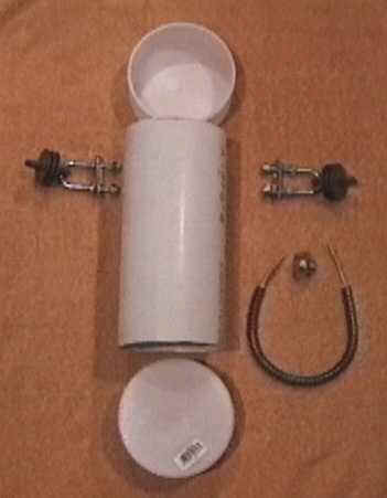
The Wireman also sells some sturdy plastic insulators (their #810) which I wanted to use as the attachment points for the wire elements. I then picked up some 1/4 X 3/4 X 2 1/4 inch stainless steel U-bolts, which would connect the insulators to the plastic pipe end caps. The following picture shows the basic elements of the plastic cylinder, U-bolts, and insulators. The picture also includes the ferrite core current choke, and the SO-239 jack. All plastic parts are 4 inch, Schedule 20, in size.
|
Components of the basic cylinder |
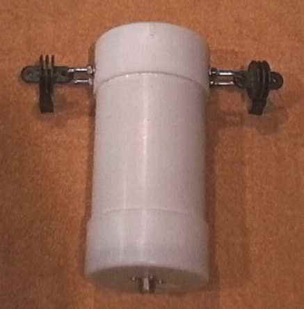
The length of the cylinder was set at 8 inches. I glued the top end cap to the pipe. I drilled mounting holes for the SO-239 connector on the center of the bottom cap. I mounted the U-bolts on opposite sides of the top end cap, half way down the length of the end cap. The following picture shows the parts assembled as described.
|
Assembled basic cylinder |
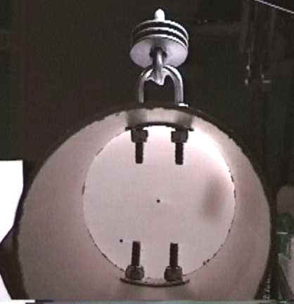
The holes on the plastic insulators were slightly enlarged so that the U-bolt could pass through them. The normal U-bolt plate is flat. Since the cylinder walls are curved, I bent the U-bolt plates to match the radius of the inside of the cylinder. I added extra nuts and washers on the outside portion of the U-bolts in order to make a firm sandwich of metal around the plastic. The following picture looks down the cylinder at the U-bolts.
|
U-bolt mounting details |
The external shell of the enclosure was complete. What I needed now was a scheme to mount the relay and inductors firmly inside the cylinder.
A number of different ideas were considered. I wanted a solution that provided a firm mount, but was also maintainable. In other words, parts could be accessed and replaced. Since the space in the cylinder was not very large, and it was 8 inches deep, it would be necessary to assemble the components outside of the cylinder. The cylinder itself could not directly be part of the mounting system.
In the end, I went with what I called the toilet paper tube dispenser design. I attached the relay and inductors to a 1/2 inch diameter plastic pipe that is held in place by 3/4 inch end caps. On the top end of the cylinder I simply glued a 3/4 inch end cap to the inside of the 4 inch cap. The bottom support was complicated by the SO-239 jack which was already attached to the center of the bottom 4 inch end cap. I created a mounting surface for the 3/4 inch bottom end cap by gluing it to a 2 inch end cap which was placed around the SO-239 connector and itself glued to the 4 inch end cap. A slit was cut in the 2 inch end cap to allow the current choke to pass from the SO-239 into the 4 inch cylinder. The next figure is a simple cross section of the mounting system.
|
Cross section drawing of the mounting scheme (not to scale) |
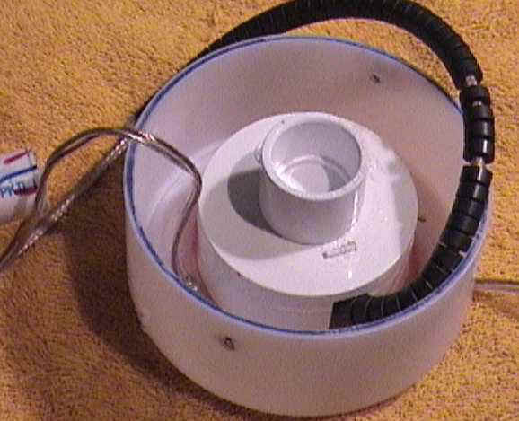
Here's a picture of the bottom 4 inch end cap showing the details.
|
Bottom end cap with mount for the 1/2 inch plastic center support |
The ferrite cores are clearly visible around the RG-303 coming out of the slit in the 2 inch end cap. The 3/4 inch end cap on the top center matches up with a second 3/4 inch cap on the top of the cylinder. These two caps hold captive a length of 1/2" pipe which will serve as the mounting base for the internal components. The two-wire cable coming through the bottom cap on the left side is the relay control cable. I drilled 4 holes around the perimeter of the bottom cap to accept #10 X 1/2 inch stainless steel machine screws that hold the bottom onto the cylinder. I also drilled a weep hole in the bottom cap, to drain any moisture that might accumulate. Water always seems to find a way to get to where it doesn't belong.
I used a hack saw and file to create a notch in the 1/2 inch pipe for the relay. Since the relay, a 10 amp Potter and Brumfield unit, came in a sealed plastic case, I simply glued it into the notch. If ever the relay fails, it will be necessary to replace the 1/2 inch pipe as well. All that was left was to mount the toroids.
Given the expected power levels, and required inductance, I selected the Amidon T225-A2 powdered iron core for the toroids. According to the EZNEC model, each toroid needed to supply 62 ohms of inductive reactance in order to lower the resonance point from 3.790 MHz to 3.525 MHz. With the wire I used, and my winding technique, each coil required approximately 7 turns. I adjusted each coil for the desired reactance with the aid of an MFJ-269 antenna analyzer. The 1/2 inch plastic pipe fits inside the core center. While the stiffness of the solid copper wire I used would probably hold the coils in place next to the relay and around the center support, I chose to pin the cores in place with 1/4 inch wooden dowels. These dowels provided a second function, which turned out to be quite important. I cut the dowel length to be the inside diameter of the 4 inch cylinder. The dowels then acted as centering guides that keep the 1/2 inch pipe centered in the 4 inch tube while the parts are assembled. The following picture shows the inductors, relay, and dowels, all attached to the 1/2 inch pipe.
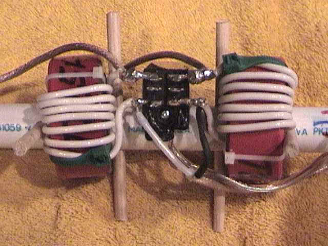 |
Inductors and relay mounted on the 1/2 inch plastic pipe center support |
In this picture, the RG-303 from the current choke, and the relay control wire, dress to the right. The antenna wires dress to the left. Two holes were drilled in the 4 inch cylinder near the U-bolts so that the antenna wires could leave the cylinder and attach to the wire elements near the plastic insulators. All internal connections are made right on the relay pins.
The antenna wires are fed through the holes in the top of the cylinder. The 1/2 inch pipe is placed in the 4 inch cylinder. The dowels keep the smaller pipe centered in the larger pipe. The current choke, which is approximately 12 inches long, winds around the inside of the bottom cap. The bottom cap is placed over the cylinder and then held fast with four screws.
I doubt if plastic pipe was designed with amateur radio in mind, but, it can be quite useful in many situations. In this case, I used it to make a strong and weatherproof case for the center support of an 80 meter Moxon Rectangle.
In this installation, the feed line runs a very short distance before it is supported. This reduces the weight of the feed line connected to the bottom cap. In the case of any significant feed line weight, I would strongly recommend that the feed line be supported by a strain relief rope that connects to the U-bolts. I would not allow significant weight to hang down from the bottom cap. In the extreme, it could crack and fail. I would also use the U-bolts as a mounting point for any upper support rope that would raise the cylinder in the air.
Back to my Experimentation Page