 |
| Coil Building Materials, Lexan Spacer Bar and Copper Tubing |
Greg Ordy
This page describes the loading coil (inductor) that I built for my center-loaded 160 meter (1.83 MHz) vertical antenna. I attempted to build a high Q coil in order to minimize losses in the coil. The unfortunate fact is that loading coils for 160 meter vertical antennas will almost always have enough loss to dissipate a significant percentage of the total power delivered to the antenna. This means that if you intend to operate at high power levels, the loading coil must be capable of dissipating it's share of that power.
While this page had been created to talk about the construction of my coil, references will be provided on the general topic of vertical antennas and the use of loading coils.
In August of 2010, an epilogue to this page was created at this link.
An antenna is resonant on some frequency when it has only radiation resistance, and zero reactance. A vertical antenna becomes resonant when it is approximately 1/4 wavelength long. Several factors influence the exact length needed for resonance, particularly the diameter of the antenna relative to the length. A fatter antenna does not need to be as long as a thinner antenna. To be a little more precise, the vertical will be resonant (zero reactance) when it is 90 electrical degrees long. The relationship between electrical length and physical length is complex, and depends upon many factors.
Let's assume that you have a resonant 1/4 wavelength vertical antenna. What happens if you start to vary it's length? Whether you make the antenna shorter or longer, it will begin to exhibit reactance at what was the original resonant frequency. If you shorten the antenna, it will develop capacitive reactance, which is measured in negative Ohms. If you lengthen the antenna beyond it's resonant length, it will develop inductive reactance. Inductive reactance is measured in positive Ohms.
There is nothing inherently wrong with using an antenna which is not physically resonant. The typical approach is to cancel the reactance with a capacitor or inductor that equals the antenna reactance, but is of the opposite sign. When the antenna develops capacitive reactance because it is made shorter, inductive reactance is added to cancel it. When the antenna is longer than its resonant length, it becomes inductive, so a capacitor is used to cancel the inductive reactance.
Please note that these are general statements subject to many factors. For example, I have not indicated where to place the canceling reactance in the physical antenna. In practice, there are many choices.
A very thin wire approximately 134 feet long is equal to 90 electrical degrees at 1.83 MHz, which is near the middle of the DX portion of the 160 meter amateur radio band (in the United States). If we could stand a 134 foot long wire straight up on its end, we would have a resonant antenna for that frequency. As you might imagine, thin wires won't stand up on end, but boy, do I wish they would. So much of antenna work would be made simpler if that worked. If we build the antenna out of a structure that can be made that tall, such as a triangular antenna tower, the good news is that the length needed for resonance will decrease, but you still have a something usually over 120 feet tall.
Since achieving this length is often expensive in materials, substantial in ground space needed to install and guy it, and possibly an eyesore to those who don't see beauty in antennas, many 160 meter vertical antennas are physically shorter, and are not naturally resonant. That means that they will exhibit capacitive reactance, and will need an inductor to bring the antenna system into resonance. Much research has gone into determining how to make a vertical antenna efficient, especially those that are inductively loaded because they are physically shorter than their natural resonant length. Some of my favorite vertical antenna references include:
The pages of L.B. Cebik, W4RNL. He has an excellent series of pages on the alternatives in loading a half-height 80 meter vertical. Efficiency improves as the loading coil is placed further and further away from the base of the antenna. In other words, center loading is better than base loading, and top loading is better than center loading, and if you have to load a short vertical at all, use a capacity hat. W4RNL uses extensive modeling to verify these results which have been presented in many sources over many years.
ON4UN's Low-Band DXing, third edition. The chapter on vertical antennas covers all aspects of these antennas. Much information is given on the relative merits of loading techniques. The conclusions follow the W4RNL pages, but the information presentation and writing style differ, as one would expect with different authors.
The ARRL Antenna Book. The best information on loading short verticals in contained in the chapter on mobile antennas.
Loading Coils for 160-Meter Antennas, Charles Michaels, W7XC, QST magazine, April, 1990. A detailed look at how one can relatively optimize the Q of a loading coil.
Vertical Antennas, William Orr, W6SAI and Stuart Cowan, W2LX. A good source of general information on verticals, with practical designs.
Vertical Antenna Handbook, Capt. Paul Lee, N6PL. Another good source of general information on verticals, with practical designs.
Vertical Antenna Classics, ARRL Publications. A collection of reprints from ARRL publications, on many aspects of vertical antennas.
Reflections II, M. Walter Maxwell, W2DU, published by Worldradio Books. Available from Worldradio's website. Also available through the ARRL. While this excellent work covers far more than loading coils, the importance of high Q loading coils comes up in several places. In particular, page 6-14 discusses the relationship between turn spacing and self-resonant frequency.
Without restating all of the excellent material in those sources, let me try to motivate the need for high Q and high power loading coils.
Regardless of the location of the inductor in the antenna (base loading, center loading, top loading, etc.), it is quite common to require at least several hundred Ohms of inductive reactance to cancel the capacitive reactance of the shortened antenna (on 160 meters). The Q of the inductor is defined to be the reactance of the inductor divided by the resistance. The Q value of a good, but not optimum, inductor might be approximately 250. If the reactance of the inductor is 750 Ohms, the resistance is equal to (750 Ohms / 250), which equals 3 Ohms. While 3 Ohms may not sound like a lot of resistance, we have to put that value into the context of the whole antenna.
Although there are many factors that control the efficiency of the antenna system, major factors include the radiation resistance of the antenna, loss in the ground radial system, and loss in any loading components used to bring the antenna into resonance. Each of these terms is measured in Ohms. A 160 meter antenna shortened to a little less than one half of its resonant length (still a tall structure) might have a radiation resistance of 15 Ohms. A ground radial system consisting of approximately 32 wires, each 0.3 wavelength long (quite a lot of wire), over good soil might have a loss resistance of 10 Ohms. In addition, we have 3 Ohms of loss resistance in the example inductor.
We can get a good approximation of the efficiency of this antenna by using the formula: Efficiency = Radiation Resistance / Total Radiation and Loss Resistance. In this case, we have 15 Ohms divided by 28 (10 + 15 + 3) Ohms, or 54 percent. So, in this example, about half of the power we send to the antenna is radiated, and the other half is wasted, heating the ground and the loading coil. The loading coil represents 3 Ohms of the total radiation and loss resistance of 28 Ohms. This is a little more than 10 percent of the total resistance. If we decided to pump 1500 watts into this system, approximately 150 watts will be dissipated in the loading coil.
Now let me stop for a second and mention that I am painting with a very broad brush. There are many factors which tilt the computations in one way or another, in particular, the location of the loading coil in the antenna. Please read the sources listed above for all of the details. Still, these numbers are not atypical. In some cases, the power dissipated in the loading coil could go up to several hundred watts. This is easy to do if the radiation resistance or ground resistance goes down, causing the loading coil to take on a larger percentage of the total resistance. The radiation resistance will go down if you make the antenna shorter, which is a natural temptation, and the ground resistance will go down if you add more radials, which is usually all that can be easily done to increase the efficiency of an existing antenna. In other words, if you improve your ground radial system, you will actually increase the power dissipated in the loading coil since it the power saved in the improved ground system will be redistributed between the radiation resistance and the loss in the loading coil. Sad, perhaps, but true.
If we can increase the Q of the loading coil to an optimized value of 800, we will reduce the loss in the coil by over two thirds. The down side to using a higher Q coil is that the bandwidth of the antenna will be reduced, but fortunately on 160 meters the needed bandwidth in the DX window is small (if you are interested in operating in more than the DX window, the reduction in bandwidth can become an important consideration).
The bottom line for me is that in typical situations, a loading coil which is part of a shortened 160 meter vertical antenna will be called upon to dissipate up to several hundred watts, assuming an input power of 1500 watts. We need to make sure that the coil can handle this power without failing. If we can improve the Q from typical values of 200 to 300 up to more optimum values of 800, we can reduce the loss in the coil by the Q improvement ratio, reducing the power handling requirements of the inductor, and providing more power for desired signal radiation.
A number of factors influence the Q and power handling capacity of an inductor. The Q is highly influenced by the relative physical dimensions of the coil. Long coils with small diameters should be avoided. An important metric is the length to diameter ratio. As the name implies, the length of the total coil is divided by the diameter of a single turn on the coil. In order to maximize Q, the length to diameter ratio should be in the range of 0.5 to 2. A coil with a length to diameter ratio of 1 is as long as it is wide. If one were to look at the coil from the side, the cylindrical shape maps into a square. For this reason, a coil with a length to diameter ratio of 1 is also called a square coil. There are no 90 degree angles in the coil, but rather the coil is as wide as it is tall - that's the square being referenced. In general, a smaller length to diameter ratio improves Q. It is also desirable to space the turns by approximately the thickness of the wire used.
Closely-spaced inductors will maximize the distributed capacitance that exists between every turn. The net effect of this phenomena is the same as if a capacitor was placed across the inductor, created a resonant tank or trap circuit. As we all know, a parallel resonant circuit greatly resists the flow of power through it (at the resonant frequency). The high resistance (impedance) at resonance will decrease on each side of resonance, both towards higher and lower frequencies. It is desirable, therefore, to operate the inductor as far away from it's self-resonant frequency as possible. A closely-spaced inductor, with the largest distributed capacitance, will tend to have a lower self-resonant frequency (than if the turns were spaced further apart). The lower self-resonant frequency may cause the impedance through the coil to rise at the operating frequency, which is exactly the opposite of what we desired.
The power handling capacity of an inductor can be increased by building it from thicker wire. At short-wave frequencies, a phenomena named skin effect forces all current to flow into the outside layer of metal. As a result, a wire tube will be as effective as the same diameter of solid wire. For all practical purposes, copper is as good as more expensive materials such as silver and gold, and is somewhat better than aluminum. Copper, however, can be more easily oxidized than aluminum. Since the impact of skin effect is that the current will flow on the outside of the conductor, copper should be protected from oxidation by a spray coating such as clear Krylon acrylic spray paint.
The last major factor influencing inductor Q is the form used to support the turns. Ideally, air should be used, but air provides no mechanical support. Forms of plastic pipe are popular because pipe is locally available, inexpensive, and supplied in a wide range of diameters. The concern with any form is its absorption of energy at the operating frequency. One of the classic tests to determine if a material is suitable for use as a coil form is to place a small length of it in a microwave oven with a glass of water. If after a minute or two of power the material is still cool (but the water may be boiling), it is probably an acceptable coil form.
In my case, I decided to use 5/16 inch copper tubing as the coil wire. This material is available in useful lengths such as 50 feet, and can be found at most hardware stores. If this tubing were given a wire gauge, it would be very close to #1 gauge. #1 gauge wire should easily carry thousands and thousands of watts without failure. This particular coil requires approximately 56 feet of tubing, so be sure to estimate your needs before making a purchase.
One of the desirable properties of the copper tubing is that it can be easily bent, and tends to hold its bent shape. This property made it possible for me to dispense with a solid cylindrical form, and instead use six spacer arms, equally positioned around the coil.
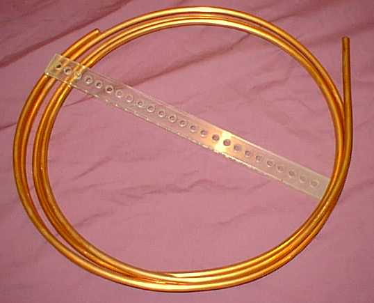
My nearby large city, Cleveland, has a well-stocked specialty plastic shop that sells exotic materials, as well as fabricates parts for a wide range of applications. The extras, ends, and experiments, end up in an outlet store. I was able to pick up long plastic bar stock which I believe is Lexan, an extremely strong plastic. The stock is approximately 1 inch wide, and 1/4 inch thick. I cut a number of 13 inch lengths. Using a drill press and a sharp drill bit, I drilled holes along the center line of the bar stock, spaced at a little less than twice the diameter of the copper tubing. A drilled length of the bar stock is shown in the following picture, along with some of the copper tubing. Please click on the picture for a larger view.
|
|
| Coil Building Materials, Lexan Spacer Bar and Copper Tubing |
The copper tubing comes coiled in a box, and the material shown in the picture was excess tubing. The out-of-the-box shape of the tubing is an important part of using it in this design. The tubing already is formed into rings, and it is relatively easy to adjust the radius.
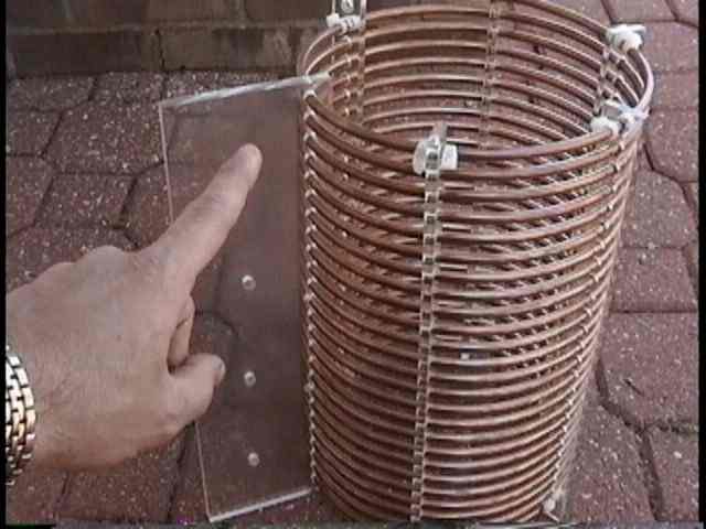
Here are several views of the completed coil. Please click on a picture for a larger view.
 |
 |
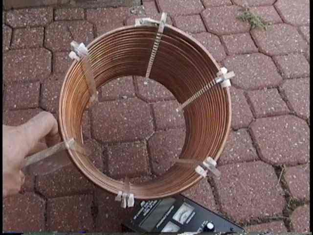 |
| Loading Coil | Closer View | Top-Down View |
The left picture shows the coil next to an MFJ antenna analyzer. One of the six plastic spacer arms was cut from a larger piece of plastic. This provided a place to mount the coil on the side of the wooden mast which is the bottom section of my vertical. I use approximately 38 feet of wooden mast topped off with 35 feet of aluminum tubing. The coil is at the electrical and mechanical interface between the two sections.
Winding the coil is a tedious process of threading the tubing through all of the holes on all six spreader arms. The radius of the coil is set in the first complete turn or two. The coil has a length to diameter ratio of approximately 1.53 to 1. This is less than the largest suggested value for creating a maximized Q value. I experimented with making the coil even larger in diameter, but found that it was too flexible, and tended to sag at the far (outside) edge of the coil. The 13 inch long coil, approximately 8.5 inches in diameter, supports itself quite well. While this was the only coil that I built using this technique, I did build a simplified prototype to help me determine the length of the coil I would need to resonate my particular antenna.
When winding the coil through the spreader arms, the arms are periodically shifted around the coil to facilitate the threading operation. Once the coil was completely wound, the spreader arms were adjusted to be equidistant around the perimeter of the coil. I used cable ties on each side of the arms to lock the turns in position. When complete, I sprayed the coil with a number of coats of clear Krylon acrylic paint, in an attempt to slow down the oxidation process.
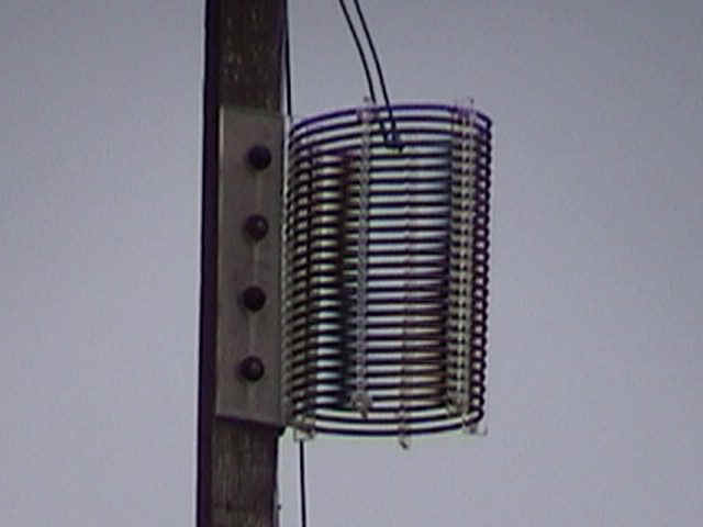 |
| Loading Coil mounted on the 160 Meter Vertical Antenna |
This picture shows the coil mounted on the 160 meter vertical. It has been in the air for approximately 5 years. Since the plastic is exposed to wide ranges of temperature and ultraviolet light, it should be of a type that does not break down under such stress.
After I had the coil up on the antenna, I started to acquire some test equipment that would let me directly measure the resistance and reactance of the coil. Since lowering the antenna is a nontrivial job, I won't be making any measurements until I take the whole antenna down and replace it with a full-size, nonloaded, vertical. I don't know if I have achieved that supposed outstanding Q of 800, but I would like to believe that I am at least at 600. My ground radial system consists of approximately 60 radials, each between 60 and 90 feet long. This is on top of rich midwest soil, over my septic tank leech field. I would hope that my ground losses are relatively low. This puts more demands on the loading coil, since it supplies more of the overall resistance in the system. With 1500 watts from my amplifier driving the antenna, I have always been able to work everything that I can hear. In fact, as is often the case on 160 meters, I spend far more time working on receiving antennas than my vertical, which I only use for transmitting.
If you are interested in seeing how this inductor survived over the years, please go to the epilogue page.
Back to my Experimentation Page