 |
| Coil After Removal from the Vertical |
Greg Ordy
On another page, I described a loading coil that I built for a center-loaded 160 meter vertical. In August of 2010, I finally lowered that antenna to the ground, in preparation for replacing it with a new vertical. This gave me the opportunity to check on how the inductor stood up against over a dozen northern Ohio years. This includes hot summers and cold and snowy winters.
Over that time frame, I have accumulated some good quality test equipment, and hopefully the measurement skills to use them properly. Of special interest to me was the coil Q, which was an important topic in the first page. I finally had the tools to measure what the first page could only wonder about.
This page describes what I discovered when I brought the coil back inside.
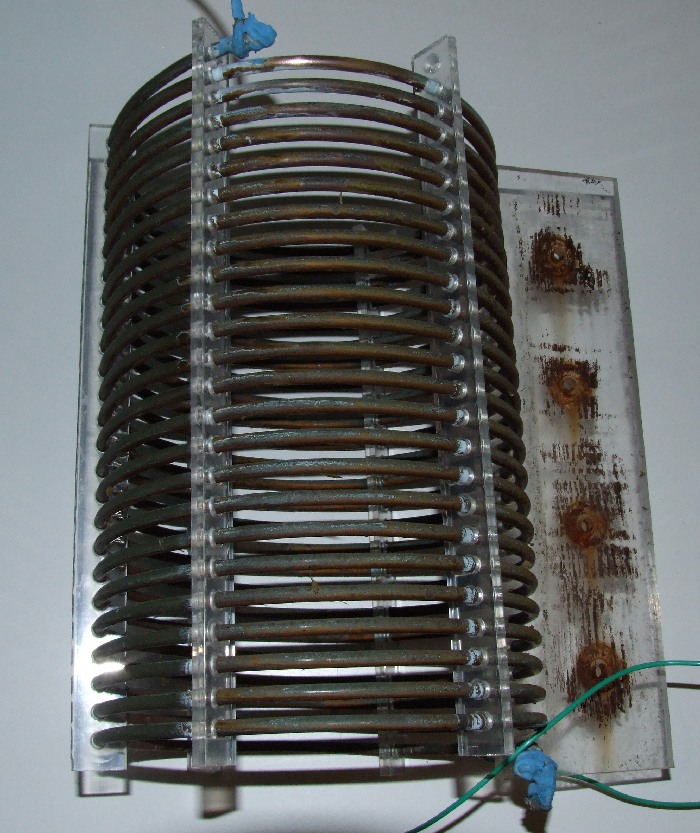
The coil survived with little signs of mechanical wear. I was amazed how good it looked. On my previous page, I showed how I had used cable ties on the copper tube to locate and fix the plastic spacer bars. All of the cable ties were now missing, no doubt having cracked and fallen off over the years of UV damage. Still, the spacer bars were evenly spaced around the circumference of the turns, and there were no problems due to spacer movement.
The plastic was in wonderful shape, with no fogging or signs of cracking. It was not brittle. I still don't know the specific type of plastic I used, but whatever it was, it had no problems being outside. I said on the other page that it was Lexan (polycarbonate). I've recently used some polycarbonate on my new 160 meter vertical, and I now no longer am so sure that the coil plastic was polycarbonate. The old plastic seemed softer, if that make any sense.
I had soldered connections on the ends of the coil that went to the antenna above and below the coil. The connections were covered with a plastic coating. The coating survived without problems, and was not brittle.
Here is a picture of the coil. Please click on the picture for a larger view
|
|
| Coil After Removal from the Vertical |
The discoloration on the mounting tab on the right is brown deck stain that was used to treat the wooden mast that held the coil. The blue globs are the plastic coating on the soldered connections.
For the record, there are a little less than 24 turns on the coil. The material is 1/4" OD soft copper tube, used in applications such as refrigerator ice maker water supply lines. The coil OD is 8.5", and it is close to 12" tall. As measured in the next section, the inductance is 70 uH at 1.8 MHz. An 8.5" OD leads to a circumference of 26.7", and with 24 turns, the approximate length of the copper tube is 641 inches, or, 53 feet. The turn to turn spacing is close to 1/4". On the first page where I described the coil, I said it was 5/16" OD copper, and around 56 feet long. I just measured the tube with a micrometer, and the OD is 0.248". Where this gets tricky is the crazy world of tubing and pipe dimensions. Because I measured a true 1/4" today, I'm tempted to call this 1/4" tubing. But, perhaps this is called 5/16" in the strange tubing world. Within reason, the difference of 1/16" is not going to be significant.
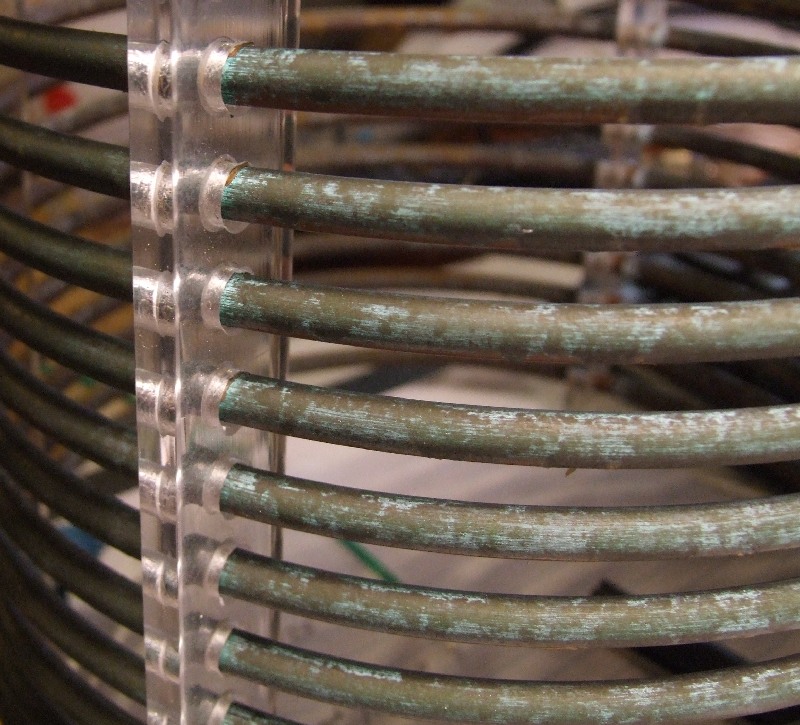
The copper tube was no longer shiny, and was obviously oxidized. When new, I had coated the coil with many layers of clear acrylic spray paint to try to slow the oxidization process. None the less, Mother Nature still worked her magic. The most obvious sign of copper oxidation is a green color. I had only a light green in broken regions along the tubes. The main indication of oxidation was that the shiny and bright copper was now dull brown.
 |
| Coil Tarnish and Oxidation |
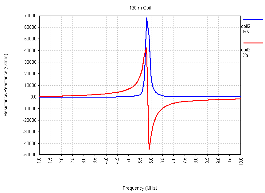
I brought the coil inside, and shined up one end to solder on a new wire so that I could get both sides of the coil near my test jig. I made an impedance sweep from 1 through 50 MHz in steps of 100 KHz to get a big picture view of the coil characteristics. Here is a graph of the resistance and reactance from 1 through 10 MHz based upon that sweep.
 |
| Coil Resistance and Reactance |
The resistance is in blue, and the reactance is red. The first page on this coil mentioned self-resonance, and now we see that this coil is self-resonant near 5.8 MHz. Above that frequency, the coil is equivalent to a capacitor, since the reactance is negative. The impedance plot is the classic signature of parallel resonance. In the context of antennas, we usually want to avoid operating near the self-resonant frequency of an inductor since it will have resistance that is due to the self-resonance, in addition to expected resistance such as in the conductor. All real inductors and capacitors are eventually self-resonant, if you find the right frequency. Capacitors are usually self-resonant at relatively higher frequencies, since their parasitic inductance comes from lead length. By keep the leads short on a capacitor, you can move the self-resonant frequency way up the spectrum. Inductors have a parallel self-resonance, and capacitors have a series self-resonance.
Generally speaking, the larger the inductance, the lower the self-resonant frequency, all other factors being equal. That suggests that we should try to minimize the needed inductance for loading or matching.
Walt Maxwell, W2DU, in his excellent Reflections book, talks about self-resonant inductors, especially in the context of mobile antenna loading coils. It is possible to create an inferior loading coil that has a lower SWR because the added resistance due to self-resonance creates an impedance closer to 50 Ohms. While the SWR is low, the dirty little secret is that the 50 Ohms is composed of a lot of loss resistance that comes from using an inductor too close to its self-resonant frequency. As they say, a dummy load has a great SWR, but is a poor antenna.
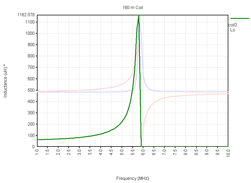
How can we get a handle on how close we are to self-resonance from the perspective of inductor quality? I like to look at the inductance curve. One of the reasons we talk in terms of inductance, measured in Henries, is that a part ideally has the same inductance at all frequencies. In other words, it's a flat line on an inductance graph. Inductive reactance, on the other hand, is always a function of frequency. Let's add the inductance data to the resistance and reactance graph.
 |
| Coil Inductance |
The green trace shows the inductance. While it is somewhat flat in the first few MHz, it peaks at the parallel resonant frequency, and then disappears, since the part becomes a capacitor. My interpretation of this sort of graph is that if I wanted to use the inductor under 3.0 MHz, the resistance (and, therefore, loss) is probably acceptable. Above that, however, the self-resonance creates a lossy inductor, and I better be paying close attention to what I'm doing. Over the last few years, whenever I find a situation where a relatively large inductor is needed, I've learned to be on watch for self-resonance. It's there, ready to bite you if you give it the chance. If you are not measuring a flat inductance as a function of frequency, then you may be seeing self-resonance.
What is the inductance of this large coil? By zooming in on the data, we see that the inductor is near 70 uH in the 160 meter band. That is a ton of inductance.
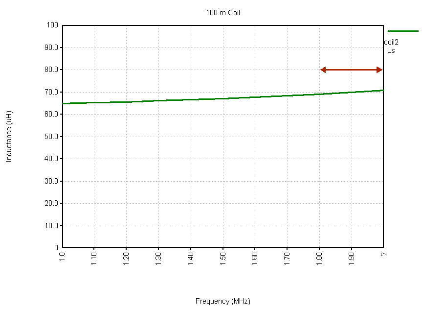 |
| Coil Inductance (1 to 2 MHz) |
I highlighted the 160 meter band with the red arrow. Ideally, the green line should be flat. It is not because lurking up a few more MHz is self-resonance.
The definition of Q, or Quality Factor, for inductors is X / R, that is, reactance divided by resistance. To have a high Q, we want a high reactance while at the same time a low resistance. Can we generate some expectations before looking at the Q graph? Well, at self-resonance, we know the X passes through 0, and the resistance is very high, near 70,000 Ohms for this coil. That results in a very low Q. As the frequency drops, the resistance drops much faster than the reactance. That improves the Q, since resistance is in the denominator. Here is the graph of the coil Q.
 |
| Coil Q |
As expected, the Q drops with frequency, and is effectively 0 at self-resonance. In the 160 meter band, the Q is very close to 300, a good, but not exceptional value, especially given all of the work it was to build this coil. By the way, what is the value of the resistance that we have been trying to minimize? The coil resistance is:
 |
| Coil Resistance |
The resistance is close to 3 Ohms in the 160 meter band. Due to self-resonance, it starts to rapidly rise with frequency. I should mention that when it comes to antenna models that include inductors or traps, I like to measure the part and then insert the actual R and X values into the model. I find this is more accurate than specifying inductance when the inductance is not flat.
When I thought about writing this page, I was planning on measuring the old coil, including a few graphs and pictures, and then be done with it - right around this point on the page to be honest about it. On the first page, I wrote that I was hoping for a Q in the range of 600 to 800. Here, we see that it measures closer to 300. So what went wrong? There could be several explanations.
First, my measurement could be sloppy. We are talking about 3 Ohms of resistance. If my test jig added let's say 0.5 Ohms of resistance, that would throw off the Q. A Q of 300 would really be closer to 360. When making measurements that will be based upon low resistance values, test fixture loss can make a difference.
Second, since I didn't know the self-resonant frequency when I built the coil, I had no way of knowing how close I was to it. All of the rules of thumb and guidelines for winding coils are designed to push self-resonance up in frequency, since it is the primary factor in low Q. The challenge is to accumulate as much inductance as we can, while minimizing the capacitance between the turns. Although I tried to follow the rules, for the amount of inductance I needed (70 uH), it was just not possible to get further away from self-resonance. Let me say it this way. By needing 70 uH, the Q was limited to a lower value. Had my vertical been longer (above the coil), and I needed only 50 uH, the Q of that inductor, following the same construction guidelines, could have been higher.
Third, what about oxidation on the coil over time? Could the Q have started off higher when the coil was new, and dropped over time? Oh boy, now I have to chase that down, in order to try and explain the Q. Well, this is an example where we might be able to see a difference, so it's probably worth exploring. The journey continues. The rest of this page is about trying to clean up the coil, and seeing if it makes a difference in the measured Q.
Why does tarnish or oxidation on the conductor matter? The first factor that enters the picture is called skin effect. This is the phenomena that causes RF to primarily flow near the outer surface of a conductor - hence the name skin effect. The Wikipedia has a good page on skin effect. Skin effect makes it possible for hollow tubing to offer the same performance as solid rods. For weight and cost reasons, this is actually a good thing, since our towers would be much more expensive if our antennas had to be made from heavy solid metal, and not lighter tubing.
Skin effect does cause us to focus on the purity of the outer layer of metal, since that's where most of the current will flow (for AC, not DC). Oxidation has the property that it penetrates some depth into the pure metal. It is not like a plastic insulator jacket that covers the metal, and has no substantial effect on the electrical properties. It is a chemical change to the metal conductor itself, and it can change the RF conductivity. Due to skin effect, it's happening at the worst possible place, at the surface.
One of the techniques used to reduce the problems associated with skin effect is to silver plate a metal such as copper. This has been a much discussed topic over the years, especially in areas such as VHF/UHF amplifier design. A page with some interesting discussion about silver plating can be found here. My understanding has always been that silver or silver plated copper is a marginally better conductor than copper, so it does not help much in a new (and shiny) installation. Over time, however, the silver plating develops a silver oxide tarnish, whereas the copper develops a copper oxide tarnish. Those two compounds are quite different in their characteristics, with silver oxide being relatively conductive, and copper oxide being very much an insulator. So, if you silver plate, it's usually for maintaining performance over time, not initial performance.
The topic of copper oxide and other related oxides and componds appears to be quite complex. The green material often associated with copper appears to be copper sulfate or copper carbonate (malachite). The copper oxidation process goes through a number of stages, and is influenced by the environment around the copper. So, my use of the term copper oxide is a simplification of a much larger process, although I think reasonable from the the perspective of conductivity.
When it came to judging the possible effect of oxidation on the coil, it occurred to me that the harder it is to remove the tarnish, the larger the electrical impact may be. I started by applying some Tarn-X, a popular tarnish removal product. Not much happened. I then switched to a metal polish that said it worked on copper. Same thing, not much happened. Finally, I resorted to steel wool. I was able to start to bring out shiny copper, but it took a lot of rubbing in a very small area. To me, this was good news, since it suggested that if it's hard to get rid of this coating, it could be a source of problems.
Since the coil turns are close together, the idea of getting around the tubing and cleaning it in any sort of mechanical way, short of sand blasting, seemed goofy. I needed a chemical answer. What came to mind was acid, especially muriatic acid (hydrochloric acid). A few quick searches on the Internet suggested that it was appropriate for cleaning copper. You do need to be careful when dealing with acid. I can think of at least two reasons why. First, splashing the acid on yourself can lead to burns or blindness, and those aren't good things. Second, the combination of acid and certain materials can create dangerous fumes. I remember back in high school, one of the smartest kids in the school dropped a penny or nickel or some coin into concentrated nitric acid to see what would happen. Whatever gas was released was poisonous. Thank you Ethan. I wonder where he is now?
The point is, be careful around acid.
My approach was to get a spray bottle with some muriatic acid, and spray it on the coil, followed by a water rinse. The hope was an easy path back to the shiny copper of the last century.
I got out my full body painting suit, and goggles, and gloves, and respirator mask, and all of the safety gear. My hose and pressure washer were standing by for rinsing. As I sprayed the coil, I started to get a lot of bubbling action, and a pool of white and green liquid when I rinsed the coil. Green is a signature color for copper oxide. Although the coil was getting cleaner, you could tell that it was not turning into bright and shiny new copper. In fact, it had sort of a pink color to it. Still, it looked better, and after it dried, I took it inside to measure it. Lo and behold, the Q dropped, which was the opposite of what I hoped for! More on this in the next section. I appeared to need more cleaning!
I then started to look at the coil more closely. It was obvious that the surface was quite a chemistry experiment. I concluded that the original acrylic paint layer was largely intact, but that oxidation was able to get under the paint as well gunk over the coating. If I used some steel wool, I could create a nice shiny copper surface, and it was less rubbing than before the acid spray. But, it was still work, and I really didn't want to get into a long labor intensive process.
I decided that rather than a quick spray with strong acid and a rinse, I needed a longer soak. So, I filled a laundry tub in the house with my hottest water, and then poured in a bottle of vinegar. I let the coil sit in that bath for a few hours. After removal and drying, I had a Q that was up to around 500 at 2.0 MHz. I concluded that this longer soak method was useful, but it was getting late in the day, so the plan was to go outside the next morning with a big plastic tub and soak the coil in water with diluted muriatic acid.
I filled up the tub and added what was left of the original quart of acid. It was a real witches brew, although there was not much action on the metal. I was using cold water as opposed to hot, and that will change the rate of the chemical reaction. I was seeing coating pieces float off of the metal. At this point, I was out of acid, so whatever state I was in after a few hours would be it. Here is a picture of an inductor in a tub of water mixed with acid.
 |
| Coil In Acid Tub |
I also noticed that the original wire soldered to one end of the coil was showing some acid abuse. The plastic coating was partially removed, and the soldered wraps were not looking too good. It might be the case that I would need to replace one or both end wires, although I could not be sure until after the soak and cleanup. Since the wires are part of the measurement, I would prefer to leave them untouched, but if the acid is creating a problem with the connection, then I really need to fix that.
After the 6 hour acid bath, I removed the coil and used a pressure washer to clean it off. It still had tarnish, although it was looking pretty good. The Q was similar to the previous reading, around 500. The coil also had that pink color. That makes me want to soak it in vinegar again, since that seemed to remove the pink before. Oh boy, this is getting complicated.
I did soak the coil one more time in a tub of hot water and a quart of vinegar. But, that's it, no more, I'm done. It looked better, but there was still a lot of discoloration here and there around the coil.
There may be better ways to clean a copper coil. I must admit, I would have liked to have tried sandblasting. Everything else was messy and unsatisfying. Our goal is an outer surface of copper that is pure elemental material. For all I know, even acid creates compounds in the outer layers of atoms that are not as conductive. I think that my various acid baths were a roller coaster ride through various conductive states. That's why I like something like sandblasting, since it's the only process the returns me to an outer layer of pure copper.
Right before I started the cleaning process I calibrated my VNA and made a sweep of the coil. Although it's always best to make an absolutely accurate measurement, in this case, like many other, we are really looking to find a change or difference. So, you want to get a calibration and testing jig that is the same for all measurements, so that those factors, as much as possible, are removed from the data because they do not change.
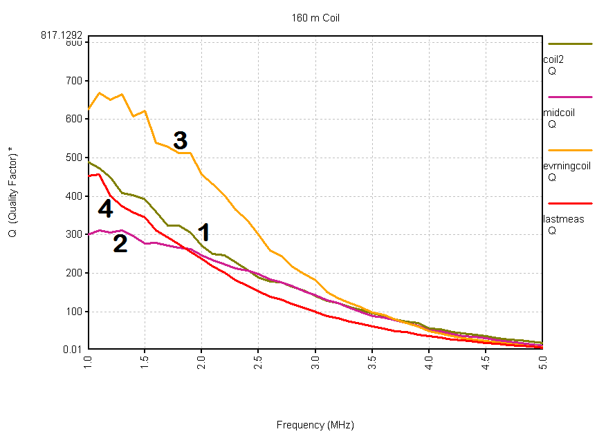
If you think that the cleaning story was a mess, the measurement story was even more confusing. Here are my results.
 |
| Q Results |
The trace labeled 1 was the first measurement of the dirty coil. After the first spraying with muriatic acid, I measured 2. After the soak in vinegar for several hours, I measured 3. The coil was then soaked in muriatic acid, and finally in vinegar and hot water for many hours. The result was 4. I should also mention that the original wire, soldered to the coil many years ago, was replaced for the last reading. It looked to be suffering after all of the acid treatment, and it was also getting flexed quite a bit as I was using it as a handle to move the coil around in the soaking tub.
The coil was being used around 1.8 MHz, near the 1 label.
So what does this all mean? I believe that the Q was being mainly influenced by the self-resonant frequency. It was close enough that I was going to be picking up resistance. A 70 uH inductance is quite high, and the higher in frequency you want to use it, the closer you will get to self-resonance. It's hard for me to believe that the coil Q was ever 600, let alone 800, at 1.8 MHz. I believe that something around 500 is reasonable. But, I do think that there is something to the copper oxide issue, and it is what I would call a secondary influence. It would have been helpful to either use this coil at a lower frequency, or, need less inductance. 160 meters can be a tough band, especially if the goal is to maximize efficiency. I still don't know the best way to clean up copper. No matter what chemicals are used, it seems as if mechanical polishing as a final step makes sense. If not, you might be leaving less conductive compounds on the surface.
The coil survived quite well, and the construction approach stood the test of time. The coil Q was probably not as high as hoped when it was built. A protective coating that would limit the weathering would be helpful. Tarnish and oxides can reduce the Q, but, the main factor is the self-resonant frequency. Every time you start to wind an inductor, you are also making a parallel capacitor. The various rules of thumb for winding high Q inductors are designed to maximize the inductance and minimize the capacitance, all in the name of pushing the self-resonant frequency as far away as possible. Although I tried to follow the high Q winding rules, I certainly don't know if you can do better than this example. I would think so. I'll say this much - I tend to wind most of the inductors I use on powdered iron or ferrite cores. In those cases, I have found that getting a high Q (usually in the range of 180 to 300) can be tricky, and sometimes the conventional wisdom winding style does not lead to the highest Q.
The only way to settle this is with a challenge - the 70 uH challenge. If you wind a 70 uH inductor with a higher Q than reported here, email me the results, and I'll create a highest score list.
This page has descended into the depths of outdoor inductor nitty-gritty. Let's step back and see what difference this all makes in the context of a complete antenna system.
I created an antenna model of a single 1" diameter aluminum wire with an inductor located half way up the antenna. This is somewhat close to my old 160 meter vertical dimensions. My 70 uH inductor provided 800 Ohms of inductive reactance at 1.850 MHz. For this antenna, I found that I needed 685 Ohms for resonance at 1.83 MHz. I fed the antenna with 1500 watts of power, and the ground type was the real MININEC ground. Initially, the inductor load had zero resistance, meaning it was a perfect part. I ran several models where I started with a Q of 600, and then slowly reduced it. For each model, I recorded the feed point impedance, the power in the coil, the gain of the antenna, and the reduction in gain from the perfect case. Here is a table of the results.
| Effect of Inductor Q on Center Loaded 70' Tall Vertical on 1.83 MHz (X = 685 Ohms) | |||||
| Q | Coil Resistance | Feed Point Z | Coil Power | Gain | Gain Loss |
| infinite | 0 Ohms | 14.32 - j0.80 | 0 Watts | 1.52 dBi | 0.00 dB |
| 600 | 1.142 Ohms | 15.36 - j0.82 | 101.6 Watts | 1.22 dBi | 0.30 dB |
| 400 | 1.713 Ohms | 15.88 - j0.83 | 147.4 Watts | 1.07 dBi | 0.45 dB |
| 200 | 3.425 Ohms | 17.44 - j0.88 | 268.3 Watts | 0.67 dBi | 0.85 dB |
| 50 | 13.7 Ohms | 26.79 -j1.24 | 698.4 Watts | -1.2 dBi | 2.72 dB |
The value of increasing the Q is not to be found in the antenna gain, since a Q of slightly under 200 will result in a signal strength drop of (only) 0.85 dB. Even a miserable Q of 50 drops the gain by 2.72 dB, which would be acceptable to many folks. What is worth watching is the power that the coil must dissipate. Even an excellent Q of 600 puts 100 watts into the coil. If you are going to be sloppy with the Q, be sure you can handle the power implications. I should say that this is very much a worst case. First of all, in the transmission line to the antenna you will lose some power. This model assumes no ground loss. Even a very good radial system will usually add a few Ohms of loss. Finally, the impedance at the feed point needs to be matched to 50 Ohms. This is typically done with a step up inductor. It will consume a little power, although not much.
What seems ironic is that the techniques and approaches that raise the Q also raise the power handling capacity of the inductor. As you need to absorb less power, you have a greater capacity to absorb power. Life is funny like that.
Back to my Experimentation Page