 |
| Anatomy of the L44PW |
Greg Ordy
The title of this page might read like some sort of secret code. I guess it's one of those pages that if you are looking for specific information you'll find the page, and otherwise you might not care.
LDF4-50A is the model number of 1/2" diameter Heliax coaxial transmission line made by Andrew Solutions, owned by CommScope. The LDF (low density foam) line appears to date back to the end of the 1970s. The cable I am using here is being reused, and I suspect that there is a lot of this cable out on the surplus market. I've seen it recently advertised between $1 and $2 per foot (even new in some cases).
Much of the coaxial cable used by hams has an outer diameter of 0.405", such as the popular RG-8 and RG-213 cables. Working along with the 0.405" cable is the even more popular PL-259 UHF plug that is inexpensive and universally available. 1/2" Heliax is perhaps the first cable you encounter as you start to increase the diameter. Increasing the diameter usually lowers the loss and increases the power handling capacity, which are good things. If there is a problem with the larger cables, other than cost and availability, it is getting companion connectors. While cable can sometimes be found for almost no cost, such as from a cable TV office, the connectors are another matter. The connector I am describing on this page is the L44PW. It is an N-male connector that is no longer made, but can be found on the surplus and used market.
This page describes the process I went through to reuse LDF4-50A Heliax and L44PW connectors. After I had functional connectors, I measured the cable to verify the typical expected characteristics. I wasn't about to put in service cable that didn't meet the specifications, or had some problem that I missed. Within reason, I could not make quality measurements until I had a stable connector. So, you do have to do some upfront work, even if the cable you have ends up being flawed.
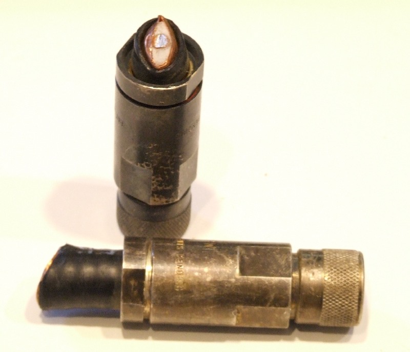
Here is a picture of a disassembled connector, and a small stub of Heliax.
|
|
| Anatomy of the L44PW |
The connector consists of the following pieces.
Outer shell with the screw on N barrel (upper left).
Insert that screws into the back end of the outer shell, and provides a compression grab of the Heliax. It has a red rubber O-ring to reduce moisture entry on the outside of the insert.
Brass center pin that is soldered to the center conductor of the Heliax. The pin comes up through an insulator on the outer shell and provides the typical N connector profile at the tip.
While not part of the connector body, there is a second red rubber O-ring that mounts on the Heliax, and is technically part of the connector assembly. It reduces moisture entry on the inside of the insert.
To the extent that there is magic involved with this connector, it is the action that happens right at the end of the Helix on the outer copper shield conductor. I have highlighted this with a red arrow. When the connector is correctly installed, the copper outer conductor of the Heliax is trapped in two ways. First, it is grabbed by the insert. You can see the separate fingers on the insert that are compressed together when the insert is screwed into the tapered outer shell. That's just the first trapping. The second, and what I believe is the most important mechanical connection, is a hard metal ring inside the outer shell that presses into the flared Helix ground tube and up against the insert. As best as I can tell, this is the primary ground connection. The Heliax ground tube is made from relatively soft copper. When a connector is installed correctly, it cannot be rotated on the Heliax, and it can't be pulled out. Without a good grab of the Heliax ground tube, it should be obvious that the cable would simply pull right out of the rear end of the insert. If you get nothing else from this page, make sure that after you install a connector you cannot rotate it or pull it off. Try - try hard - make sure you have a good mechanical ground connection, leading to a good electrical connection. The second most important installation aspect is to make sure that the center pin is fully up against the insulated stop so that the standard N connector dimensions are presented.
The connector is silver plated, and quite a nice part. It feels good and solid.
I've had a long suffering project to replace my 160 meter vertical. One aspect of that is to replace the original feed line, which was 9913 coaxial cable. The vertical took some lightning damage a few years ago, and the cable suffered serious damage from it, and is no longer usable.
In general, I've been thinking about the idea of slowly upgrading to better cable as part of ongoing station improvement. The criteria that I had set after thinking about it some was that it would be worth it to replace a section of cable if I could lower the dB loss by 1/2. In other words, if I had a run with 1 dB of loss, then unless I am willing to reduce it to 0.5 dB, don't bother. If the run has 0.001 dB loss, I need to reduce that to 0.0005 dB. Those are rather impossible numbers, but I wanted to illustrate my thinking.
In this case, I was replacing 9913. Comparing 9913 to LDF4-50A at 1, 10, and 50 MHz provides the following table.
| Attenuation per 100 ft | ||
| Frequency | 9913 | LDF4-50A |
| 1 MHz | 0.2 dB | 0.064 dB |
| 10 MHz | 0.4 dB | 0.205 dB |
| 50 MHz | 0.9 dB | 0.463 dB |
Down at 1 MHz the LDF4-50A is a 3X improvement, but settles into a 2X improvement at higher frequencies. I'll be using it at 1.8 MHz, so, it definitely meets my loss reduction goals. By the way, at 2 MHz, LDF4-50A can handle 25 KW, so there are no concerns over power capacity either. At that point, the connectors become the power limiting factor.
9913 is probably a rather odd choice for 160 meters, since it's usually considered a VHF/UHF cable, due to low loss. It is one of the lowest loss 50 Ohm cables in the 0.405" diameter family, so the LDF4-50A clearly takes us to a new level of performance relative to the common cable diameter. But, you pay for it in terms of more exotic connectors.
I obtained the 1/2" Heliax from the estate of a ham and great guy up the street, Val, W8KIC. There were three lengths that were coiled up in his garage for at least 10+ years. Val had been using 7/8" Heliax out to his towers, and this thinner cable was left over from previous installations. I didn't know much about it, but it looked to be in good shape, and since I could measure it's characteristics all I needed were connectors. One length was just about perfect for the new run at my house, and I figured that was a sign that I should use it.
After some Internet searching, I came across various LDF4-50A connectors at RF Parts. This is hardly a surprise, since RF Parts carries most everything in the RF cable/connector area. I've ordered frequently from them over the years, and always been very satisfied.
Their LDF4-50A page shows several connectors, going from N series at around $16 (USD) per connector to UHF series connectors at $34 each. I was interested in two listings, the L44PW-P and the L44PW-P1. The first is a surplus (removed from service) L44PW that has been cleaned up by RF Parts for $13 each. The second is the same connector, but you get to clean it yourself. The price now drops to $9. I purchased 10 of them, so the price further dropped to $8.50. The folks at RF Parts said that they had a lot of these available, but remember that the information I am providing here is as of May, 2010.
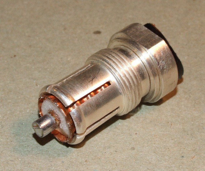
What showed up in the mail were 10 connectors that looked just like this. Please click on the picture for a larger view.
 |
| L44PW on Arrival |
You can see the cut end of the LDF4-50A cable coming out of the end of the connector. By the way, the center conductor of the cable is copper clad aluminum, which is one of the reason why the cable is not overly heavy. The connectors were heavily tarnished, but that's to be expected for silver plate. A shiny silver plated connector will start to darken after just sitting for a day.
These connectors were in service, and cut off right past the connector. I spent some time trying to find official assembly instructions. I was unable to find such a document. It is probably out there, and contacting Andrews is probably the best idea (I did not do that). RF Parts did not have any info, and I view them as pretty definitive. I was glad that I ordered the connectors that required cleaning because in taking apart a working end I could reverse engineer how to put them together. This page really is about saving those instructions for future reference.
Let's put these loss numbers in terms of watts so that we can see how crazy I might be. In order to use published loss numbers, let's say that I'm going to use the cable at 1 MHz, and that I'll be using 150 feet of cable (that is close to the real value). Loss is linear with distance. A cable with a certain loss will have double the loss if you double the cable length. This assumes uniform cable, which should be a very safe assumption.
Let's further assume that I will be driving the cable with 1500 watts. That's going to be optimistic since I need to go through about 200 feet of other cable just to get to the start of the 160 meter run from an intermediate switching box. But, we have some numbers to play with.
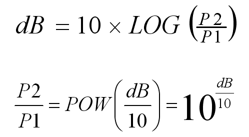
The formula for taking a power ratio and computing dB, and the inverse formula is:
 |
| Power/dB Loss Formulas |
For 150 feet at 1 MHz, the 9913 loss would be: 0.2 + 0.1 = 0.3 dB. For 150 feet at 1 MHz the LDF4-50A loss would be: 0.064 + 0.032 = 0.096 dB. We can use the second formula to convert from dB to a power ratio by dividing the dB value by 10, and then using the POW function, which is really base 10 exponentiation - that's probably how it shows up on a pocket calculator (10 to the X power). Now before I do the division I'm going to negate the dB values since we are talking about loss. So, we want to use the 10 to the X function with values of -0.03 and -0.0096. The results are 0.933 and 0.978. These two values are the power ratios for -0.3 and -0.096 dB. So, if we were to apply 100 watts into something with 0.3 dB loss, out would come 93.3 watts. If we applied 100 watts to something with 0.096 dB loss, 97.8 watts would survive. That's a loss of 6.7 watts per 100 with the 9913, and 2.2 watts per 100 with the LDF4-50A (for 150 feet of cable). These numbers should not surprise, since they are the factor of 3X we started with.
For 1500 watts, the 9913 loss is 100.5 watts, and the LDF4-50A loss is 33 watts - again for 150 feet of cable, at 1 MHz.
A loss of 1 dB is very close to 20%, so we would need to lose around 300 watts out of 1500 to be down 1 dB. The 9913 is 1/3 of that, and the LDF4-50A is 1/3 again of that. By going from 9913 to LDF4-50A, I'll be saving around 66 watts of power, if I'm sending in 1500. This is for 150 feet of cable at 1 MHz.
Ok, perhaps a better title for this section is hams are clever. Due to the expense of real connectors, many novel alternatives have been developed over the years. When I was taking apart the existing connectors and checking the cable for holes in the outer jacket or other problems, I found one of the classic Heliax/UHF homebrew connectors.
 |
| Homebrew Heliax UHF Connector |
The connector is based on 2.5" of 1/2" copper plumbing pipe. Each end is slit with a hacksaw to provide a compression fit with hose clamps.
On the left side, pointed at with the red arrow, is a good old UHF barrel connector. The Heliax is prepped with a long center conductor that is shoved into the end of the UHF barrel. The example cable shown here, if actually used, would need a much longer center conductor to reach the UHF barrel. The Heliax center conductor must be reduced in diameter to fit into the UHF barrel. This can be done with a file.
Perhaps the biggest problem with this approach is weatherproofing. Several layers of tape or other protection is needed if this connection will be outside.
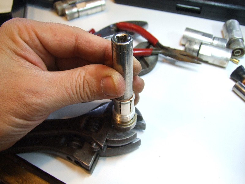
The L44PW insert is removed from the shell with a pair of wrenches. I used adjustable wrenches without any problems. The insert uses the standard right hand thread direction. The size of a fixed open end wrench appears to be 21 mm. Yes, as best as I can tell, the connector is metric. This will come up again when we look at the ridges on the ground (shield) tube.
If there is a trick in the disassembly phase, it is getting the old stub of Heliax out of the insert. Because the Heliax has been deformed out of round when it was cut, the little stub can't be driven through, it has to be backed out. But, as indicated in the first picture on this page, the end of the tube has been flared open, and is larger than the normal tube diameter. That means that it really doesn't want to back out, and there is not much of a stub hanging out of the back for grabbing
The technique I used was to put the connector over some adjustable wrenches set to support the insert shoulder, but not touch the Heliax. A bench vise is an alternative. The center pin was desoldered and removed, mainly for its safety. I used a deep well socket to drive the stub of Heliax out of the insert. The next picture shows the set up, right before smacking the socket with a hammer. You can click on the picture for a larger view.
 |
| Removing the Old Heliax Stub |
There may be a better way to do this, but this worked for me. I should mention that you should plan on spending around 15 to 20 minutes per connector for disassembly and cleaning.
Desoldering the center pin is not any special challenge, but you do need a lot of heat. More on this later during the assembly phase.
Try not to damage the two red rubber O-rings that are part of each connector. I found mine to be quite supple and in good shape. If damaged, I would think that typical hardware store O-rings could be used.
The L44PWs required cleaning. They are silver plated, which tarnishes quite quickly and easily. I searched on the Internet for cleaning tips, and many web pages went through a procedure where you boiled the item in water mixed with baking soda, salt, and a small piece of aluminum foil. I decided against any boiling action because the outer shell contains a rubber bumper washer on the N connector opening, and an insulated insert that holds the center pin in place. While I suspect these could stand a lot of abuse, I didn't want to boil them.
I resorted to two store bought chemicals, a relatively thick polish/cleaner, and the famous Tarn-X. Combined with a soft brass brush and Q-Tips, the connectors cleaned up nicely. Here is a picture of what I used to clean them up. The brass brush really helped quite a bit. I suspect that you can damage the connector plating with too much force, but for cleaning sake, it works well.
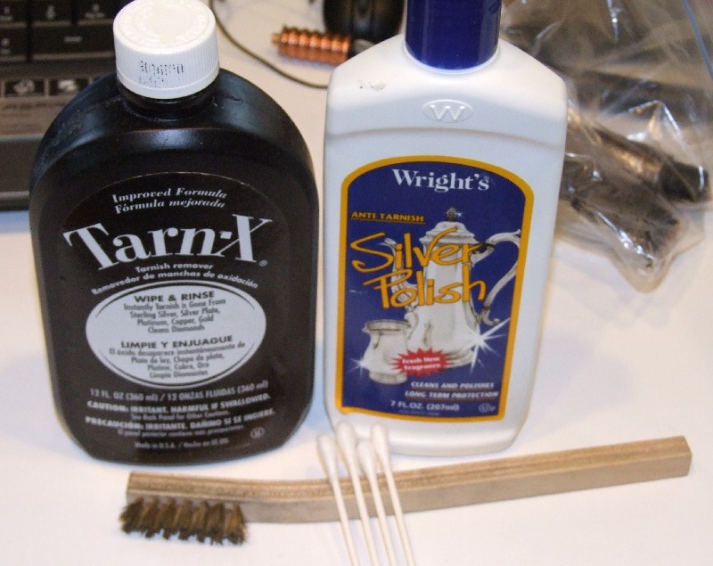 |
| Cleaning Supplies |
I spent some time doing an initial cleaning and checking of the cable. In the end, I want to verify the electrical parameters, but something like a large gash in the outer jacket, or a crushed section would cause me to reject the cable, or at least the damaged sections. I cleaned the cable with a typical kitchen surface cleaner, and then wiped it down with an Armor All style product. This gives the jacket a nice glossy shine that makes it easier to spot certain flaws and defects.
I ran my fingers up and down the cable a few times, feeling for any problems with the jacket. I did not ask the cable to turn its head and cough. I also checked for crushing. With the solid copper shield, this type of cable probably would not rebound after it was crushed.
In the end, the pieces I had picked up all checked out OK on a first physical inspection. To the extent that I found problems, it was in the last few feet of the cable, and it was easy to just trim off some questionable cable. In my application, the cable will be placed on the ground, so any holes in the outer jacket will sooner or later lead to problems.
I lined up all of the stubs that I removed from the connectors, and tried to determine how to prep the cable end. Of course I was assuming that the person who prepped these stubs did it correctly. That's probably a safe bet, and I had many to look at, so I could take an average if necessary.
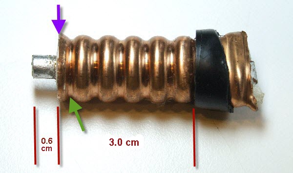 |
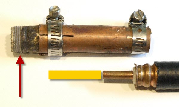
| LDF4-50A End Dimensions |
From what I could tell, the reference point for the connector is the end of the copper shield tube, indicated with the purple arrow. That point is designed to match the widest point of the copper corrugation. This is also very close to the end of the insert. The end bumps on the insert fingers drop right into the first corrugation narrowing following the end, indicated with the green array. The key aspect is that the widest point on the copper tube be at the end of the insert. With the proper prep tool, the open end of the tube would be slightly flared open to accept the ring in the outer shell. This is the mechanism that traps and grabs the shield. If the copper diameter is not wide enough at the top of the insert, the ring can't grab the tube between the inside and outside surfaces.
The center conductor extends past the copper tube by 0.6 cm. The distance from the end of the tube to the start of the jacket is 3.0 cm, or 6 corrugation bumps. This is another reason why the cable appears to me to be metric - the corrugated ridges on the copper tube are 0.5 cm apart.
The tool I used to cut the jacket and the copper shield is a pipe cutter. This tool needs to be used carefully. When cutting the jacket, cut through the jacket, but don't score the copper. When cutting the metal end, it's necessary to be sure you are at top dead center of a corrugation (the purple arrow). It's easy for the cutter to slip into a valley between corrugations. The tube must be cut at the middle of a wide section.
One of the problems with a pipe/tubing cutter is that it always tends to shrink the diameter of the material it is cutting. It pinches as it cuts. In this case, this is the opposite of what we want. We want to flare open the end, not pinch it closed with a tubing cutter. This pinching will be fixed later when we are ready to install the outer shell.
I used a hand coping saw with a fine tooth metal blade to cut off the center pin. If any sort of burr is left, it can be filed off after the cut.
One of the issues with working with this cable is that it is relatively stiff, and bends with a large radius. Usually, with 0.405" diameter coax, it's possible to twist and bend the cable to make it align with your tools and workbench. With this Heliax cable, you can't get away with so much mechanical manipulation. So, tools like the pipe cutter are desirable because they work easily in any orientation. You have to bring the tools to the work, it's hard to bring the work to the tools, and some particular human alignment.
To prepare an end, I suggest the following steps.
Move in about 2" from a cut end and locate a corrugation high point on the jacket. This is not too hard to detect, because the corrugations telegraph through the jacket. Use the tubing cutter to cut the jacket at a high point. It may be necessary or desirable to use a shape knife or diagonal cutters to cut down the jacket to the tubing cutter slit. Remove the outer jacket. The cable can be cut with a hacksaw, or any cutter with a metal blade. Using any form of scissor action cutter probably won't work because it will deform the tube out of round as it cuts. A sharp knife could probably be used in place of the tubing cutter.
Move in 3 cm or 6 corrugation bumps from the end of the jacket, and locate the high point on the copper tube that will become the end of the tube. Use the pipe cutter to cut the copper tube at that point. If you slip off of a high point on the copper, especially towards the jacket, you must start over if you start to cut into the metal. Remove the cut end, and using a sharp knife, remove the foam around the center conductor. It does appear possible to cut in a corrugated valley, if you do it to the long side, away from the jacket. In that case, there is simply more copper to peel back and flare out. This may be the better way to prep the end since there is abundance of copper to grab. At the worst, you need to do some trimming with a sharp diagonal cutter to dress the copper. Here is where I wish I had an official picture of the proper preparation. All I can do is look at the used ends I have.
Cut the center conductor to a length of 0.6 cm from the end of the copper tube. This should also be the same point as the end of the insert. If they are not the same, the insert appears to be the better reference. This might be a little long, since if it's too short there's not much you can do about it. If it's too long, you can file it down later.
After you have the end at this point, you can put on an insert and see if it grabs the first corrugated valley after the end of the copper tube. You might find that you need to trim back the outer jacket just a little. In other words, that 3 cm distance might be a little short. You'll know if there is a problem because you can't push the cable far enough into to the insert for it to click onto the last valley. If there is a problem with these connectors, in my opinion, it is that there is no protection against water and moisture getting in under the outer jacket where it starts. So, I want the jacket to butt up against the insert as much as possible. Further down this page I use some adhesive-lined heat shrink to protect this junction. Still, I like a nice tight fit at the butt end (no jokes please).
 |
| Prepared Cable End |
This example is what I consider to be the best prepared end of the lot of reused connectors. Please click on the picture for a larger view. The end of the copper tube appears to have a wave in it. That's the result of the clamping action between the insert and the outer shell. So, this example is post clamping, not pre clamping.
I found it useful to practice preparing ends on a scrap piece of cable. With each end you get a little better, so try a few practice preps before you get to the real cable.
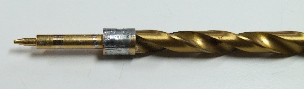
I need to mention the preparation of the brass center pin. It is the only part that is soldered. When it is removed from an end, it will still have some solder inside the end cylinder, and if you try to push it back on the center conductor right after removing it, it probably won't fit because the solder has become solid and reduced the inside diameter just a little. To remove that solder, I found that the best solution was to use a drill bit as a reamer. Here's where you need a good selection of bits to find one that is just the right size. You want to remove solder, not brass. Here is a picture of the drill bit in the end, doing its work.
 |
| Drill Bit Cleaner |
Keep applying the bit until the brass pin fits completely over the cable center conductor. It should not be loose, but it does need to seat completely on the center conductor. The brass pin does have two side holes that allow solder to flow to the inside surface.
Install the insert on the cable end, and, if necessary, trim back the jacket to get the fingers to fully seat into the corrugation. Oh, be sure to put the smaller O-ring on the cable, one or two corrugations from the jacket. I use a sharp diagonal pliers to trim off any excess copper and dress up the end to be flush with the insert and to have a slight outward flare. I suspect this is a step where having the correct preparation tool would lead to a faster and probably better result.
 |
| Dressing the End |
When I have it looking good, I measure the center pin to 0.6 cm and cut it with a coping saw with a metal blade. If necessary, trim and dress the end of the conductor so that the center pin fits over it. At some point, be sure to put the larger O-Ring over the insert. Before I solder the center pin, I screw on the outer shell. This gives me a chance to evaluate the grip on the cable, and, to make sure that the center pin is not loose with a sloppy fit. I carefully grab the center pin and try to pull it in and out of the connector.
 |
| Checking for Center Pin Slop |
Hopefully, there is no slack on the pin. If there is slack, you can either recut the end, or, try to solder the pin slightly pulled off of the center conductor to compensate. If the center pin is not fully pushed out, you run the risk of a poor connection with the mating female pin. Assuming the pin location is good, I remove the outer shell and apply flux to the center conductor before soldering the center pin with a large 175 watt iron. It always seems better to have a lot of heat available and apply it quickly and precisely to the target area, as opposed to a wimpy heat source that ends up melting the dielectric foam while waiting for the solder to flow on the pin.
Screw on the outer shell, and you are done. I make a serious attempt to rotate the connector on the cable, and even pull the connector off of the cable. There should no wiggle on the connector. It's now time to test the cable.
It was a lot of learning and work to get to the point where I had an N connector on one end of the cable intended for the 160 meter vertical. That was really just the start of the next phase which was testing.
With a single connector on one end, the most obvious tests were:
Assuming that I get acceptable values, I would then install a connector on the second end. This would allow me to make transmission measurements through the cable, which should yield the most accurate loss estimates.
The loss measurement is perhaps the most important parameter, so I'll present it first. I actually measured it last, since it required connectors on each end to make a transmission measurement through the cable. The measured length of the cable was 146 feet.
The loss standard was an N female to female barrel connector. It defines the 0 dB level. When the barrel is replaced with the cable, the loss is due to the cable, as compared to the barrel, which is assumed to be very low. Here is a graph of the loss from 1 through 50 MHz:
|
|
| Measured LDF4-50A Loss versus Published Data for 146' |
I added published loss data from a specification sheet for 146 feet of cable. The blue arrows point at the locations of the published loss at 4 selected frequencies. The measured data is right in line with what is expected.
A second method of evaluating loss is to measure the return loss of the cable. This is a single port reflection measurement. It is the signal strength of the reflected wave detected at the start of the cable, where the signal is injected. The termination at the far end of the cable should be either an open or short, since both should represent a 100% reflection of energy. We want the loss to be due to the cable, not to the load. This measurement is suggested when it's hard to gain access to both ends of a cable at the same time, and route them to the measurement device. Consider a transmission line running up a tower, where both ends terminate in connectors. If there was a desire to check the loss, it would be relatively easy to connect a VNA to the cable at the bottom, and have a person apply the open or short at the top of the tower.
If a cable had no loss, and the load was perfectly reflective, all of the transmitted energy would be returned. This would be like yelling ECHO into a canyon, and finding that the return echo is the same strength as your original signal. In addition to the return signal level, there is a delay until you detect the reflection. This will be a measure of the electrical length of the cable. That can be converted to the physical length through the cable velocity factor.
Return loss is a round trip measurement, since there is loss going from the transmitter, down the cable, reflecting off of the far end, and then traveling back on the cable. So, to compute the one way loss, the return loss should be divided by 2. Since return loss is a measurement of loss, I like to see it expressed with a negative sign, although it is commonly seen with a positive sign, since the word loss implies negative. We all know it's about loss, not gain, so if I say that the return loss is 5 dB, we assume that means that the return signal was detected 5 dB down from the transmitted signal, implying a 2.5 dB loss along the example cable in each direction. Between the factor of 2, and the positive/negative business, a return loss specification, unless explained, can be confusing.
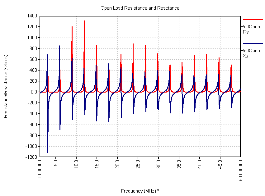
For the cable I'm testing here, the measured return loss for an open and short termination is:
 |
| Measured LDF4-50A Return Loss versus Published Data for 146' |
The pink trace is the return loss with an open termination, and the blue trace is the return loss with a short. The wave on the data is related to measuring transmission lines with high SWR, and these lines have an infinite SWR, since the terminations are an open and short. I have found it valid to draw a line through the crossing points of the open and short, and I did that with the green hand drawn line. I took the loss numbers from the previous graph, and multiplied by 2, to create round trip values. I then highlighted those on the graph with blue arrows. Again, the measurements check out, and confirm that the cable is in good shape.
Although this cable is probably several decades old, the measured loss is still very close to the published specification, and gives me a warm and fuzzy feeling about reusing this cable.
The procedure for computing a cable Zo based upon measured impedance values is described on another page. I measured from 1 through 50 MHz, in steps of 100 KHz, once with an open end, and then again with a shorted end. The resulting resistance and reactance data for the open was:
 |
| Measured LDF4-50A Impedance for an Open Termination |
And for the short:
 |
| Measured LDF4-50A Impedance for a Short Termination |
The responses show a parallel resonance form whenever the cable length and load (open or short) transform to an open circuit at the input. Alhough there appears to be a pattern impressed on the data peaks, remember that the step size is 100 KHz between points, and how the samples fall against the overall response can create alias effects.
The Zo of the cable is computed by multiplying the complex open impedance by the short impedance, and then taking the square root of the product. This is done for every frequency point. I use an Excel spreadsheet to handle the math and graphing. The graph of the computed impedance (resistance and reactance) as a function of frequency was:
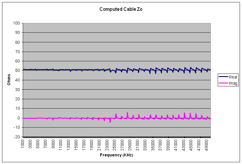 |
| Computed LDF4-50A Zo |
The averaged impedance value was: 50.8 - j 0.35 Ohms. The published impedance for this cable is 50 +- 1 Ohm. The program TLDetails, based upon published parameters, computes a Zo of 50 - j 0.16 Ohms. The cable I tested clearly is within specification, and qualifies to be called a 50 Ohm cable.
In my application, the particular velocity factor is not important, but I like to check it just as another sanity check that everything is looking good on the cable. The velocity factor relates the physical length of a cable to the electrical length. If the waves in the cable traveled at the speed of light, the velocity factor would be 1. For real coaxial cables, typical values are between 0.66 and 0.88 because the waves are traveling slower than the speed of light. Open wire line usually has a velocity factor above 0.9 (90%). The LDF4-50A cable has a published velocity factor of 0.88.
In order to relate physical length to electrical length, I needed to measure both with as much accuracy as I can get. Using a 100 foot tape measure, the physical length of the cable was 146 feet.
To measure the velocity factor of the cable, I use a distant to fault tool that is part of my VNA software package. I set the velocity factor to be the published value, and then compare the predicted cable length to the actual. If the velocity factor is correct, the predicted and measured cable lengths will agree. Here is the captured screen shot:
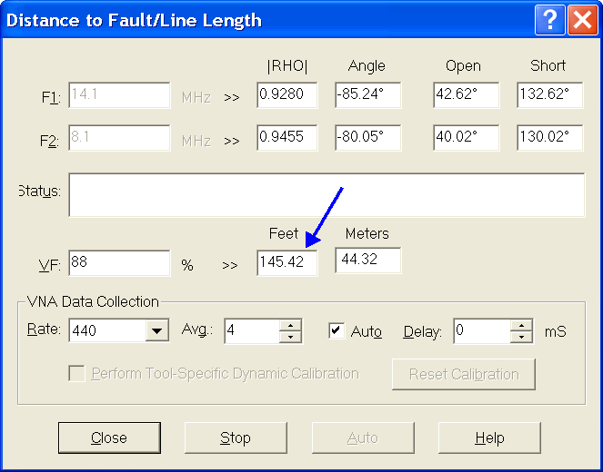 |
| Measured LDF4-50A Velocity Factor |
The published velocity factor was entered into the program, and the claimed cable length was 145.42 feet. I measured 146 feet. The error is within 1/2%, which confirms the velocity factor for this section of cable.
Based upon these measurements, I'm willing to say that the cable meets the specifications, and is ready for a new use.
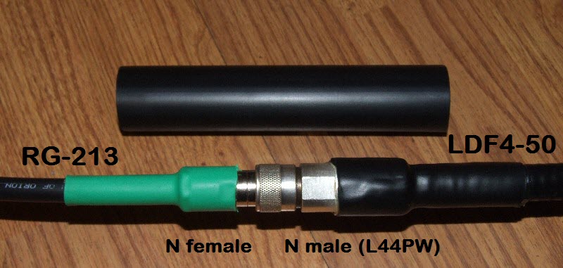
As you move beyond the 0.405" diameter cable family, the cables usually start to become relatively stiff and rigid. When you roll them up, you have at least a 4 or 5 foot diameter circle, and sharp bends could cause damage. This means that the larger diameter cables quite often have smaller diameter pigtails on their ends to allow for easy bending and manipulation at the point of ultimate connection. These pigtails can also be a place to transition between various connector families and genders. That is true in my 160 meter vertical situation as well, where I'm going to transition to RG-213 at the ends of LDF4-50A. The RG-213 can easily bend upwards to meet switching and control boxes, and I can move from N family connectors back to UHF.
For the interface between the two cables I had two choices. The LDF4-50A ends with the L44PW which is an N male; that is a given. I need to get onto RG-213. The two most direct approaches seemed to be:
Solution #1 uses a somewhat exotic adapter, that is, an N female to an UHF female. These are a little harder to find, but I found some, for the cheapest prices, at Ham World, Inc.
Solution #2 uses a clamp on N female connector that I've not used before. So, there is some risk in trying something new. On the other hand, Solution #2 has a single junction, whereas #1 has two junctions - one on each side of the adapter. So, on the theory that fewer junctions are better, I'm going with the second solution.
The N female clamp on connector for 0.405" cable is made by many sources, and is known by many names and numbers. The connectors I bought came from CableOrganizer.com.
Much like the L44PW, the 0.405" N female connectors have a soldered center pin and a compression clamp on the braid. Instructions for assembling these connectors are are little hard to find, but I was able to obtain them from CableOrganizer.com.
After the pigtails were installed, I made a final check of the overall three section cable impedance and loss, looking for any problems caused by the connectors and connectors.
I think we've all used heat shrink tubing from time to time over the years. A few years ago I became aware of a version that has an adhesive lining. This stuff is great, because it makes a water tight seal and increases the strength of the covering. Variations include increased wall thickness, to the point where it is very suitable for direct ground burial. My two usual suppliers of heat shrink are BuyHeatShrink.com and CableOrganizer.com. The adhesive can be removed, although it takes some work. Still, I would rather remove anything instead of removing a big wad of Coax-Seal.
Here is an example of using adhesive lined heat shrink over the end of a PL-259. The cable, RG-142, is a high power Teflon cable that uses a reducer with the connector. The heat shrink keeps any moisture from the reducer, and provides mechanical support due to its thickness.
 |
| Heat Shrink over PL-259 and RG-142 |
If the application requires an accessible L44PW, I would recommend a section of medium wall adhesive heat shrink placed over the butt of the connector and onto the coax jacket. This completely inhibits water from getting at the cut jacket. Here is an example, using 1" diameter heat shrink:
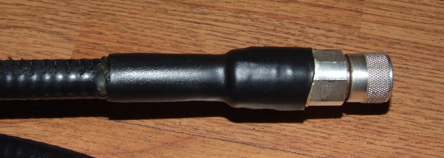 |
| Heat Shrink over the L44PW and LDF4-50A |
In my case, the pigtail connections will be lying on the ground, so I want to water and weatherproof the entire assembly, from jacket through connectors back to jacket. I used 1.25" OD heat shrink for this second layer. Over that, I'll add an outer layer of electrical tape, which is really for animal protection and general mechanical abuse. The medium wall adhesive heat shrink will waterproof and protect the connection. Here is a picture of the heat shrink next to the transition from LDF4-50A to RG-213. Like Fort Knox, nothing is getting in there.
 |
| Heat Shrink next to the adapter junction |
The heat shrink was placed over the junction and then shrunk down with a heat gun.
I should mention that you can't go too crazy with the heat shrink since it does add a lot of heat to the cable in the area around the tubing. Melting jackets and even flowing solder is not out of the question.
Heat shrink is also sold as a function of the amount of shrinkage. Common values are 2:1, 3:1, and 4:1. I've seen ratios as high as 6:1. These ratios compare the preshrunk diameter to the post shrunk diameter. In some cases it's necessary to carefully consider the specs, especially in cases of mixed diameters. On one hand, you need a piece large enough to fit over all of the diameters, on the other hand, when the tubing shrinks you want all of the diameters to be firmly gripped. The higher shrink ratios usually command a higher price, and, may have fewer options with respect to color, adhesive lining, and wall thickness. So, you can end up spending some time picking the right part.
I've noticed a product on BuyHeatShrink.com that claims to be heat shrink tape. This is a tape roll with adhesive lining that shrinks when heated. It can be applied over cables without having to break the cable to insert a tube - tape can be placed over an unbroken cable. I've not tried this product myself, but it looks to be useful for creating waterproof splices when you aren't working at a connection.
Let me mention one topic that has been a problem for me, mainly because I didn't see it coming. It's only a problem when adhesive lined heat shrink is used over more than one diameter. I call it heat shrink creep. The thicker the heat shrink, the bigger the problem.
When the adhesive is heated, it turns into a goo that acts more like a lubricant than glue until the temperature drops. At the same time, the tubing is shrinking over different diameters. At the junction between different diameters, the desire of the tubing to shrink will cause it to shift down the tubing, flowing easily on the hot glue layer. The heat shrink literally slides itself towards the smaller diameters.
Consider the following example:
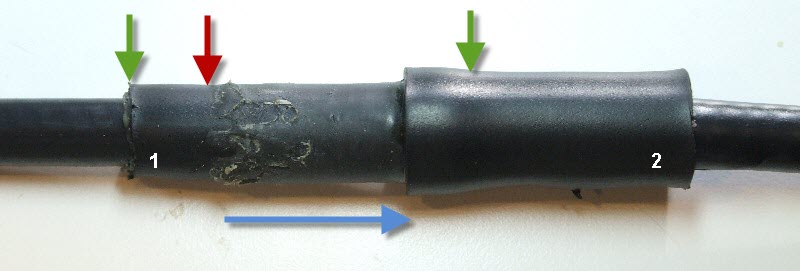 |
| Heat Shrink Creep |
The inner cable is a piece of 0.405" coax. To it, I added a piece of heat shrink that has the white number 1. This heat shrink extends from the left green arrow to the right green arrow. I then took a second piece of adhesive lined heat shrink and put it partially over the first heat shrink, starting near the red arrow. This is heat shrink number 2. I heated the second tube, and it started to shrink, and the glue started to flow. On the right side, by the right green arrow, the outer tube was able to step down to a lower diameter because the inner layer of heat shrink stopped. To allow the outer tube to shrink, it started to slip right, so that more and more tube could find a smaller diameter. It moved the distance of the blue arrow all on its own! In effect, it deposited its glue, and then slid over and off of it to the right.
The solution to creep is to be prepared to hold the tubing in place as it shrinks and cools. This can be tricky because the various parts are hot and gooey. Another solution is to have a symmetric set of diameter changes so that any tendency to move in one direction is balanced by a tendency to move in the opposite direction. This naturally happens when you have heat shrink over a thin cable, then connectors, then the thin cable again. The heat shrink can't move in both directions at once, so, it stays in place. This assumes that heat is being applied uniformly to the heat shrink. Applying even heat to the larger tubes becomes its own challenge.
If you have wires and connectors that need weatherproofing, and won't be touched for a long time, consider the adhesive lined heat shrink. It's really tough and will keep out moisture. There are version with special coatings for extreme UV and various chemical protection.
The reused Heliax and connectors look great, and measure like new. Since the loss is at least 1/2 of the lowest loss 0.405" cable I was aware of, it's a good upgrade, especially if you can find a cheap source for the cable and connectors.
Back to my Experimentation Page