 |
| Thumb and Surface Mount Resistor (no thumbs were injured in the making of this picture) |
Greg Ordy
Although I've built a lot of electronic projects, going back to a Heathkit HW-100 amateur transceiver in 1970, the N2PK VNA was my first experience with construction based upon surface mount technology. The terms surface mount technology (SMT) and surface mount device (SMD) appear to be both used to describe construction based upon soldering parts to traces (called lands) on the top of a printed circuit board, as opposed to soldering wires on the bottom of a board after they have been guided through holes in the board. I personally prefer SMT to SMD, since I tend to think of SMD as storage module drive, a computer disk drive architecture going back almost 20 years.
SMT can be used to implement digital and analog circuits. Perhaps its only drawback is that the power handling capacity of the devices tends to be low, since the parts are physically small. For digital and many analog circuits, that restriction is not a problem. In fact, traditional capacities such as the classic 1/2 watt resistor are far more than needed for low power circuitry. Surface mount resistors can have a rating of 1/16 watt. Because the traditional wire leads are no longer used, the parts lose their convenient handles. Stripped of wire leads, and reduced in size and power capacity, the physical dimensions of the board can shrink dramatically. All of these trends are good news for considerations such as cost, packaging, portability, high frequency operation, and power supplies.
All we need is a way to assemble them. If you need a lot of boards, commercial machine assembly makes sense. The experimenter and hobbyist usually assembles by hand.
As I started to search the Internet for surface mount assembly information, I was amazed to see that there were several different approaches. At one extreme, assembly is performed as if this were a traditional board with holes, which is to say that you solder one part and one lead at a time, moving from part to part until complete. At the other side of the spectrum, a board is populated with all of the parts tacked in place with solder paste. That board is then placed in a toaster oven, which is used to heat the work to a temperature where the solder paste melts and flows to make connections, but, the temperature is not so hot that the parts fail. The oven must be controlled precisely, especially compared to making a pot pie.
Even though I started off a bit concerned about my ability to assemble such tiny components, a little practice convinced me that this was nothing to be feared, and it can even be fun. While it certainly starts off slowly, I do believe that SMT hand assembly can be as fast if not faster than traditional (through hole) PCB assembly.
Building SMT boards does require the right tools, and they may not be the same tools used in traditional board assembly. I'm far from a SMT expert at this point, but I'm over my initial apprehension.
|
|
| Thumb and Surface Mount Resistor (no thumbs were injured in the making of this picture) |
This page assumes a good working knowledge of general soldering techniques.
In this and the following pictures, please click on a picture for a larger view.
This is not an exhaustive enumeration of construction approaches, but just a short list of what I've seen described on the Internet.
My initial approach solders each pin, one pin at at time. This is the most direct adaptation of traditional (through hole) construction.
Some folks apply solder quickly and liberally, covering all of the lands, no doubt creating solder bridges. Then, a second pass with solder wick removes excess solder. This approach reminds me of the instructions a friend once gave me for tightening manifold bolts on my car engine. He said: tighten them until they start to loosen up, then back off half a turn.
There are techniques where solder is applied with a larger tool, covering several pins at once, relying upon the fact that solder will tend to naturally aggregate around the pins, and create separate connections due to surface tension as the solder cools. This approach seems especially attractive (and perhaps necessary), when soldering ICs with many pins and very small spacing between legs.
In the commercial world, hot-air is used to activate solder paste. The board is generally heated to bring it close to the soldering temperature. Apparently a normal clothes iron, turned upside down, can be used. Solder paste is used to hold the parts in place prior to soldering. A special tool which can blow hot air is directed at the connections, and the extra heat of the tool sends the solder past the soldering temperature. A commercial hot-air soldering tool can cost hundreds of dollars, but there are homebrew solutions (see the Hot-Air Pencil frame) that can be made for as little as $20 (USD).
The most novel technique that I've heard of uses a toaster oven to heat the entire board so that solder paste flows, completing the solder joints. The solder paste acts as a weak adhesive to hold all of the parts in place prior to heating in the oven. This is a home version of commercial reflow soldering.
A very good link with general information on soldering is: A Primer on Hand Soldering Electrical Connections, by David Pippen. More specific to surface mount assembly is the page: A Brief Introduction to Prototyping with Surface Mount Technology, by Luke Enriquez, VK3EM.
One of my favorite pages is Using Surface Mount Parts, but Eric Seale. This page has lots of good information, but also lots of good links. SMT Assembly Techniques lists implementation approaches. Another great site is Leroy's Engineering Web Site. Not much on SMT, but tons of other hard-to-find information.
If you are going to try the toaster oven method, a good overview, as well as links to parts suppliers can be found on the Stencils Unlimited web site. They provide stencils which can be used to limit solder paste to only the contact point (lands) with the surface mount parts. This will lead to a cleaner result. Their site has a good technical article on SMT assembly.
Another view of home assembly with the toaster oven can be found at: Have You Seen My New Soldering Iron?, by Kenneth Maxon. Lots of detailed pictures.
The toaster oven technique is an example of reflow soldering, where solder paste is applied to the connections, and heated to first drive off the liquid that carries the solder, leaving the solder which soon flows. Solder paste is not the same as solder flux. Solder paste includes solder.
Many Internet stores sell SMT assembly related products. One that I've used is Circuit Specialists. They have a very good selection of chemicals used in SMT, as well as other parts, supplies, and tools. Another of my usual suppliers is Jameco. In this area, they have a nice selection of magnifying lamps, soldering irons and stations, and surface mount parts.
Most of what makes working with SMT difficult is the small size of the parts and traces. Many of the part sizes make grains of rice look big by comparison. Even if you have the eyes of an eagle, magnifying devices will be needed to work with SMT. Going along with external magnification is good illumination. In radio we often say: if you can't hear them, you can't work them. The analogy here is: if you can't see them, you can't solder them.
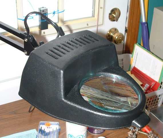
In my way of thinking about it, there are two different types of magnifying devices. A fixed device is held by a mounting arm, and you position your head over the magnifying glass, and your work goes under the glass. It's as if some very nice person is holding a magnifying glass for you, all day long. The other type of device is worn directly on your head. Lenses can flip up and down, either in position, or out of the way.
For me, I prefer the fixed devices. Most include illumination bulbs, so the light source is in front of the lens, and aimed at the work. I don't like the devices that are worn on the head because my eyes try to adjust when I stop looking at the work, and that ends up contributing to eye strain. It's also true that there is a relationship between magnification and distance from the work. Higher magnifications usually require getting closer to the work. With the headband device, you have to drop your head very close to the action. Too close in my opinion. Still, I have a headband mounted magnifying device, and from time to time, it is the right solution for a given problem. Many of the headband magnifiers have small light bulbs on each side of the headband. They just don't seem very effective.
 |
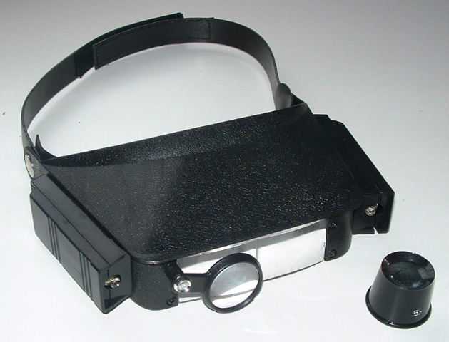 |
| Magnifying Glass with Integrated Illumination | Magnifying Headband with Illumination |
When soldering, I prefer a 2 to 3 X magnification factor. Sometimes it is necessary to closely inspect a solder joint for problems. When this happens, I use a 5 X single-eye magnifier used by jewelers (shown in the lower right corner of the right picture).
The size of the magnifying glass also matters. Four inches seems to be a minimum to see what's going on. When both eyes get involved, that stereo optic effect kicks in, and depth perception helps out quite a bit.
The best magnifiers have a 5 or 6 inch glass lens, and a round fluorescent bulb surrounding the lens. These seem to cost between $30 and $60 (USD). I have a plastic model with a 4 inch glass lens, and a 60 watt incandescent bulb. Not quite as good, but available for as little as $10 at surplus outlets.
Silver-bearing solder behaves differently than pure tin-lead solder. It will require a little more heat to flow, but I find the transition to flowing to be much more obvious than with the non-silver solder.
When I first started to think about soldering SMT devices, I assumed that a fancy (expensive) soldering station would be essential. Indeed, you can buy an expensive soldering station. It appears, however, that they are not necessary. They are useful in commercial situations where fast warm up saves time, and sturdy construction is needed because the station is turned on 40 hours a week, week after week. In some cases, having very precise control over temperature is desirable, and the professional stations usually let you specify the tip temperature, as opposed to the wattage of the iron, which is a more indirect and approximate expression of heat.
For home assembly, the most important characteristic is having a fine tip. Typical pencil soldering iron wattage ratings will be fine. That is, 15 to 40 watts.
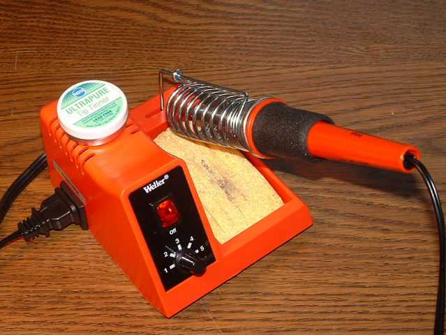
I worked backwards, starting with looking for a very fine tip which was mass marketed by a popular manufacturer, on the theory that I wanted to be able to easily obtain replacement parts. The Weller 1/32 inch conical tip looked about as small as I could go. That tip fits into the Weller 40-Watt Soldering Station, which is really nothing more than a pencil soldering iron with a simple power control, iron rest, and sponge. The power control varies the wattage from 5 to 40 watts, which is claimed to be 350 degrees F to 850 degrees F with the supplied iron.
 |
 |
 |
| Soldering Iron | As little as it gets | Solder and Supplies |
The WLC100 soldering station is shown in the left picture. I have taped a tin of tip cleaner to the top. Along with the moist yellow sponge, the tip can be kept clean and sharp.
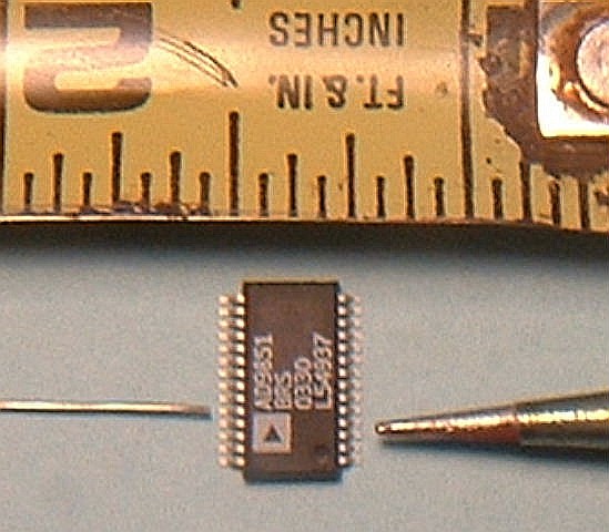
The middle pictures shows the solder and tip next to the AD9851 DDS chip, which has the smallest legs in my current VNA construction project. The solder and tip can cover a single pin without slopping over to adjacent pins, but it is a tight fit. The chip has 28 total pins, which means that 14 pins on one side are crammed into less than 3/8 inch.
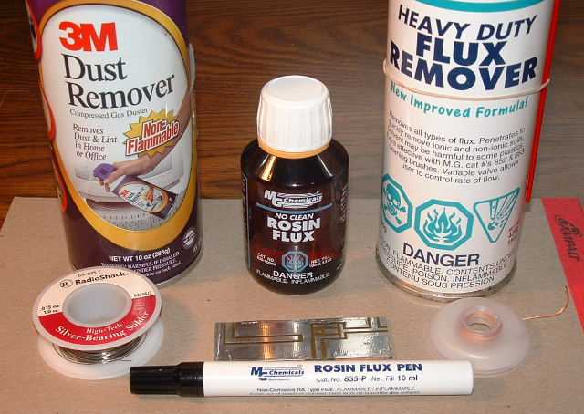
The right picture shows the solder and supplies that I've found useful. The solder is 0.015 inch silver-bearing solder made by Radio Shack (64-035E). In general, silver solder is becoming more common because there is a drive underway to remove/reduce lead from all products. While silver-bearing solder may have slightly improved conductivity, and it is much stronger than pure tin-lead solder, it does have a slightly higher flow temperature. Note: this solder, and as best as I can tell, all solder of that thin diameter, do not have a rosin core. The solder is simply too small to support a core of flux. This means that external flux is essential. In the foreground of the picture is a flux pen. This pen looks like a standard magic marker, but the fiber tip can be pressed into the barrel which releases liquid flux to wick down into the tip, and onto the board. I paint the lands with flux right before attaching a part.
If you are going to used compressed air, be sure that there are no loose surface mount parts in the area, or, they will be blown to Kansas, or at least onto the green shag carpet, which will never reveal its secrets. Liquid rosin flux is useful for board tinning, since you can easily cover a large area with a Q-Tip. Even a no clean flux will require some clean up. For that purpose, alcohol, or a flux remover can be used. The flux remover I have claims to also clean mechanical contacts, so it has multiple applications.
If you need to remove solder, there are two common choices, a solder sucker, or, solder wick. Solder wick is shown in the picture. It is made from fine copper braid which tends to easily suck up solder, to a degree where the solder is encouraged to leave where it doesn't belong, and penetrate into the wick.
When assembling traditional circuit boards, one of the most important tools is a very sharp, precise, and small set of diagonal cutters to trim off excess leads. In SMT work, there are no leads to trim. Some circuits may have wires on one side of the board, or even going through the board. These will require a good pair of cutters. Otherwise, there is very little cutting, which is unlike working with most electronic parts.
An X-Acto or hobby knife, can be used to remove surface mount parts from their carrier strips. Since these parts are so small, they are usually not sold in units of one, and in any case, then are targeted for machine assembly, so the parts come embedded in a paper or plastic carrier tape. The parts must be liberated from the carrier before assembly. I find that a sharp blade can separate the tape into top and bottom pieces which release the part. Be careful. Should a part hit the floor, I think the chances of recovery are very small. I suspect that green shag carpeting disappeared due to swallowing up small parts, as well as small children, small animals, and small cars.
I use very small tweezers to move parts onto the board. Once in place, I use dental picks to hold the part down until the first connection is made.
Another special tool which can come into play is a drill with very small bits. If you need to make a lot of holes, it's worth it to get a small drill press, or other support which allows you to drill vertical holes. If you sense of vertical is good, a hand drill will work just fine. All of the bits I have were purchased at ham fests. Get an assortment of small bits. It's hard to predict what you will need up front.
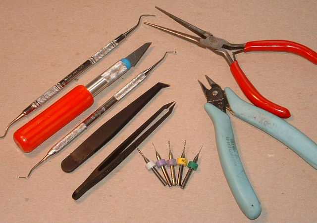 |
| SMT Tools |
Five carbide wire drills are shown in the lower center of the picture. I purchased these at a ham fest, 20 drills for $5 (USD). So long as you don't flex them, they will last forever.
When a wire is needed on an SMT board, a popular choice is 30 gauge wire wrap wire. This wire is small, strong, and the insulation resists heat. Many colors are available.
From time to time, various additional tools will be needed. The key phrase is small. Small pliers, small files, small clamps, small everything.
Most of these tools can be picked up for very little cost at ham fests or surplus outlets.
Unless your board comes with detailed assembly instructions, you will need to come up with your own assembly order. The order seems to naturally form from the simultaneous application of several rules. Here are some of the rules that I use.
Inside-Out: Work from the interior of the board to the exterior. The idea is to not have already soldered parts in the way, to the great possible extent. A variation on this is some sort of left to right and front to back order which also installs parts in an order so that they are not blocking each other during installation.
Short to Tall: Assemble shorter parts first so they are less likely to get in the way.
Generate Heat Early: Some parts, due to their size, might require the application of additional heat. Try to do these earlier, so that the heat does not spill over to surrounding smaller parts and dislodge or damage them.
Parts of the Same Type: If possible, install parts of the same type at the same time. Some parts are not even labeled, and if you get them mixed together, you can't sort it out. So, once you begin working with a certain part, install all parts of the same value. Keep everything else off of the desk.
When soldering, the iron tip comes in from an angle of between 30 and 60 degrees. All of these rules are designed to avoid the case where the tip cannot gain access to a connection at the correct angle because an existing part is in the way. As we say in the nut and bolt business, then you are screwed.
No matter what you do, have some sort of scheme to know when you are done. Leaving parts off of the board speeds up assembly, but tends to cripple functionality. Either have precise parts count, or a checklist which confirms that each part was assembled.
Before assembly begins, the board should be tinned and clean. I've described the tinning process on another page. If the board is very dirty or oxidized, a very fine steel wool pad can be used to clean it up. Whatever you do, be sure to remove all residue from the pad. Another alternative is the more abrasive scouring pads (NOT SOS, but like nonmetallic Scotch-Brite (tm)). Some sites advocate cleaning the board with alcohol. A flux remover or general electronic cleaner can also be used.
The hardest part of working with surface mount devices is holding the part in place while making the first connection. Once the part is secured in position, everything becomes easy. Well, easier.
I begin by selecting the next part to assemble, and getting it out of the carrier and next to the board. I use the flux pen to paint flux over the lands. Tweezers move the part into position. Be sure to check for the correct orientation and polarization (if applicable). Once the part is in place, I use a dental pick to apply slight downward pressure to the part. The soldering iron is brought to the part/board junction, heating both, and the flux. Because the board is tinned, there is enough residual solder to make a temporary connection. The part is now in place. If there was any shifting, be sure to move the part before you make a second connection. If the board is not tinned, or of you cannot get enough tinning solder to flow (hard to believe), then you need to deposit some solder on the land before attaching the part. Deposit a very small amount of solder, and when you do heat it a second time to solder the part, apply some downward pressure to make sure that the part is flush with the board, not sitting on a pool of solder. If it's on a pool of solder, then the part will not lie flat on the board, which can cause problems with other connections to the same part.
With the part held in place by a single connection, I spin the board around and solder the other side of the part. These connections are traditional in that I heat the part/board junction, and bring the solder into the mix after a few seconds, and wait for a good flow over the connection. I then spin the board around again, and redo the first connection, using additional solder this time.
This is the procedure for components such as resistors and capacitors. Integrated circuits are a little different. The suggested approach is to begin by soldering diagonal corner pins. This should be done so that the device pins are aligned precisely over the lands. Once the corners are soldered, and the part is aligned, you can do the remaining pins in any order you desire, just so long as you don't skip any of them.
It's important to keep IC legs (the pins) terminated on a single plane. If a leg gets bent out of the plane, it can cause trouble. The worst situation is when a leg is bent up from the plane of the other legs. In other words, it doesn't want to lie flat on the board. Some downwards pressure on the leg itself may do the trick, but the tool (dental pick) pressing down on the leg may conduct away enough heat that getting the solder to flow may be a problem.
I check each connection after it is made. As with all soldering, do not let a connection move or flex while it is cooling, since a cold solder joint may result. If possible, and if you have the time, check each part after assembly with the appropriate meter. This is usually easiest with resistors. In many cases, however, there may be circuit paths already present on the board which alter the measured values. For example, let's say that there are two 100 Ohm resistors which are placed in parallel to create 50 Ohms. After soldering the first resistor, you should measure 100 Ohms across the traces connected to the resistor. When you add the second 100 Ohm resistor, however, the measured resistance across either part will be 50 Ohms due to the parallel combination. The idea is to look for two problems. First, a poor connection. Second, a part destroyed by too much heat.
The solder connection should present a shiny concave profile, indicating that the solder surface was pulled towards the joint as it flowed. Round blobs of solder are usually a sign of a bad joint. Capillary action should suck the flowing solder into the joint voids, as well as around it. The so-called interstitial regions. I never get to use the word interstitial.
After a part is soldered with more than one connection, it is nearly impossible to move. The problem is that you cannot heat all of the points at the same time to allow the part to become free. As one heats, the others cool. One of the commercial solutions is the SMT tweezers, which are tweezers integrated with a soldering iron. With this device, you can heat up two surfaces at once, as well as mechanically grab and lift the part as soon as the solder flows. Tweezers seem to be popular for removing parts, as opposed to adding them. I have yet to need a pair, and seeing as they can be costly, I hope to avoid having to purchase one. If you are using a hot-air reflow device, you can usually get several connections to flow at the same time. I could probably try to use two soldering irons at the same time, but that leaves few free hands to snatch the part once it is loose.
Once a side of the board is complete, I use the flux remover to clean off any flux residue, and leave the connections shiny and bright.
Manual surface mount assembly is not hard, so long as you have the required magnification, good illumination, and the right tools. You know, that's true for most things in life. I wonder why it took me so many years to understand that?
As I become more confident with my approach, perhaps I will experiment with the more exotic techniques. The toaster oven method is very appealing, since it seems to be so fast and uniform. I suspect that unless a person does a lot of surface mount construction, however, it simply doesn't pay to develop that technique.
No matter what technique you use, inspection of each connection, as well as inspection for solder bridges is strongly advised. In my connection at a time traditional approach, inspection happens as each connection is made, and solder bridges are detected as they are made, if they are made at all. The other approaches, where connections tend to be made in groups, also require inspection. The danger is that some connections are missed when they are made in a group. This is especially true for the toaster oven approach, since an entire side of a board is done at once. This means that all connection must still be checked for problems after the board comes out of the oven. Once an oven is used for making boards, no longer use it for making food.
Thanks to Paul, N2PK, and Harold, W4ZCB, for help and suggestions in getting started with SMT hand assembly.
Back to my Experimentation Page