|
|
|
Control Box Schematic |
Control Box
Greg Ordy
This page describes the control box located at the base of the 160 meter vertical. I wanted the box to contain the following features for the antenna.
When the antenna control power is removed, the antenna will be grounded. This is to favor sending lightning energy to ground, even if I lose power, which is more likely during electrical storms. In other words, it would be more risky to require power to put the antenna into grounded (safety) mode, since power might be unavailable when safety mode is needed.
It is possible to electrically float the antenna. I want to be able to make the vertical electrically invisible on all bands. For 160 meters (for receiving antennas), the vertical should be floated. For 80 meters it should be grounded at the box, as in feature #1.
When the antenna control power is removed, a dummy load will be connected to the line going back to the radio. This is to provide a dummy load for general tune up purposes, and to protect the transmitter in the case of a fault with the control box or control cable, while the transmitter is in operation. In other words, the transmitter should see either the dummy load or the antenna, both of which are safe.
It will be possible to inline a small series inductor to shift down the resonance of the vertical by a few dozen KHz. In case the bandwidth of the vertical is not wide enough to cover the band to my liking, this feature provides a second SWR dip at a lower frequency.
The box will contain a matching inductor to provide a 50 Ohm match. This inductor is part of an L network that matches the lower impedance of the vertical to the 50 Ohm feed line.
The control cable will pass through an RF choke.
The transmission line will pass through an RF choke.
The box must be easily removable. The external connectors are antenna wire, ground, transmission line, and control cable. This feature simplifies maintenance.
If you add up all of the switching, and put two relays in parallel for the grounding duty, you end up with 5 SPDT relays. Two for grounding, two for inserting the shift down inductor, and one for switching the feed line between the dummy load and the antenna. While I've been known to install relays in a dead bug style with point to point wiring, for this project I decided to make a small PCB, using the tools and fabrication services of ExpressPCB. This would keep the circuit small and tidy, and should it be damaged by some future lightning hit, it would be relatively easy to drop in a replacement.
I created the following schematic for the control box using the ExpressPCB tools:
|
|
|
Control Box Schematic |
The image may be difficult to read due to the reduction in size to fit on the page. Please click on the schematic to display a full size image.
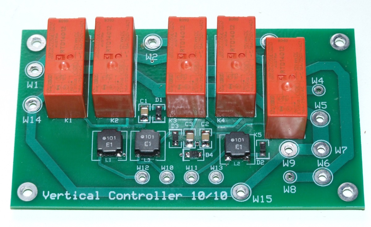
The board is controlled through a 4-wire cable that has a common ground and 3 signal wires. The true or on signal levels are +12 VDC. The control signals are named Shift Down, Online, and UnShort.
Relays K1 and K2 (on the left side) are paralleled to provide more current carrying capacity. I am using the popular appliance relays that have 16 amp contacts in the SPDT form factor. K1 and K2 are turned on with the UnShort signal. Relays K3 and K4 switch the shift down inductor in series with the signal path. K3 and K4 are turned on with the Shift Down signal. Relay K5 selects between the antenna and a 50 Ohm dummy load, and is controlled with the Online signal.
A number of wire terminals are used to make the off board connections. These are labeled W1 to W15. The antenna connects via W1. Ground connections are made via W14 and W15.
Diodes D1 to D3 are the typical snubbing diode that clamp reverse voltage spikes when the relays are turned off. Diode D4 could be called a logic diode, since it guarantees that if the Online signal is on, the UnShort relays will also be on. This was done because there appeared to be no value in having Online on and UnShort off. In this case, we would be driving the transmitter into an open circuit since the antenna is connected to ground. So, D4 is a form of additional safety. It could certainly be left off. 100 uH inductors and 0.01 uF capacitors are used to filter and decouple the control lines, although the entire control cable is also coiled around a clamp on ferrite core. The inductors have a 1 amp current rating. While that is hardly small, I do like to think of them also as fuses, should some major surge decide to try and flow by them.
The LMatch inductor is used in the matching network and is described on the Models and Measurements page. All of the inductors will be described on that page.
Two coax cables connect to the PCB. The radio is connected via W8 and W9. The dummy load is connected via W4 and W5. For both of these cables I used RG-142 coax. It is a small diameter coax with a high power rating. The cable going to the station, coming off of W10 through W13, is wrapped around a clamp on core to provide an RF choke.
Each of the relays has an approximate current draw of 33 mA at 12 VDC. We can now create a table of current requirements for each control line.
|
Control Signal Current Requirements at 12 VDC |
|
| Signal | Current |
| UnShort | 66 mA |
| Online | 99 mA |
| Shift Down | 66 mA |
The Online signal is the highest because it also turns on UnShort. The maximum current would be 165 mA, since we have 5 relays, and at most, they are all on. That's around 2 watts of power. These current and power levels are very low, and there should be no need for special wiring, unless it is very very very long. In my case, there is probably 400 feet of wire between the radio and the control box. It is a mixture of various cables that can easily handle the required power.
Here is a truth table for the Online and UnShort signals.
| Control Signals Truth Table | ||
| Online | UnShort | Meaning |
| off | off | Radio sees dummy load, antenna is grounded |
| off | on | Radio sees dummy load, antenna is floating |
| on | X (don't care) | Radio is connected to antenna (Shift Down is now useful) |
The ShiftDown signal can be turned on at any time, but it will only be useful if the antenna is Online.
The assembled printed circuit board (PCB), which measures 4.25" X 2.5", looks like this:
|
|
|
Assembled Control PCB |
I should mention that to get the PCB fabrication service with silkscreen and soldermask layers I needed to purchase 4 PCBs. I have one in the control box, and one as a spare, leaving two blank boards. If you are interested in this design, I would be happy to sell you a blank PCB for $40 (USD). That might seem like a high price, but, it's a little less than what it cost me. That's the downside of using a small-batch rapid turn around fabrication house, the first few PCBs are costly.
Although I used surface mount parts, which often times implies small and wimpy, these parts have the necessary ratings. The capacitors have a 1 KV rating, and the inductors are at 1 amp. The diodes have a 50 volt PIV and 1 amp of forward current.
I decided to wrap the control lines and the feed line around mix 31 clamp on cores. The use of RF chokes has become a hot topic that is often confused and misunderstood. I think it's fair to say that in most cases similar to this that chokes are not needed. In some installations, they are helpful. In a very few cases they can make a problem worse. What is that problem? It's the problem of RF current (antenna current) flowing on the outside braid surface of coaxial cables, or, in a common mode on other cables (such as the control cable in this case). Ideally we want antenna current flowing only on the vertical and on the radials, no other conductors. Unfortunately Mother Nature doesn't respect words like transmission line or control cable, and make those exempt from carrying currents that we don't want them to carry. Chokes, appropriately applied, break up lines into smaller, less resonant sections, and prevent current that is flowing from joining other currents at inconvenient places - such as at connectors on the back of a radio. In the case of my vertical, I would venture a guess that choking the two box cables is not necessary for the normal antenna current reasons. On the other hand, adding them will not make it worse, and, the chokes will help with my paranoia about potential lightning damage. Have you noticed that yet? Anything that sits between the house and the antenna, and in the slightest way impedes the passage of massive current pulses, even at the price of self destruction, is good in my book. If nothing else, I think that the chokes will help out in that function.
I happened to have several of the ferrite mix 31 clamp on cores that have become popular for choking purposes, especially on the lower HF bands. What I usually do to evaluate a choke is to wrap a range of turns around the core and measure the impedance response, as if I were building an inductor. The typical trend is that more turns leads to a higher impedance, but, with a narrower bandwidth that drops in frequency. This leads to the question - so how much choking impedance do I need? That is a good question, and one that could be the subject of several pages. For now, I'll just say that a few thousand Ohms would be just fine. Since this is a 160 meter antenna, however, creating an effective choke for that band is more difficult since it usually implies a higher number of turns for the same ferrite core material. And, not to make this too long and complicated, but exactly what frequencies do we care about? For example, the 160 meter vertical transmission line might not carry any antenna current when used on 160 meters. But, it is possible (even if unlikely), that when a nearby 20 meter Yagi is used that the 160 meter feed line has a substantial 20 meter resonance that causes it to carry 20 meter energy. So, the problem that needs attention could be reducing the flow of 20 meter energy on the outside of the 160 meter transmission line. It all depend upon the circumstances.
I had two clamp on core sizes on the shelf, and I decided to use one of each, the smaller being assigned to the control cable. For the purposes of identification, it's time to be specific about the cores. The ferrite cores are made by Fair-Rite. Both are mix 31, which is a rather recent mix. It has become popular for the lower frequencies since the permeability is 1500. Compare that to 850 for mix 43 and 125 for mix 61. Generally speaking, that creates a higher impedance at lower frequencies for the same number of turns. The cores I'm using are split into two pieces, and are enclosed in a plastic shell with a hinge. I've seen amateur radio pages call them clamp on cores, although Fair-Rite uses the term Snap-It. There are around a dozen parts in the same line - that is, mix 31 clamp on cores. The cores can be purchased with and without the split. I have two at the large end of the range. What I'm going to call the big clamp on core has a 1" diameter hole, and has the official part number of 0431177081. What I'm going to call the small clamp on has a center hole of around 3/4", and carries a part number of 0431176451. Here is a picture of the two, each shown in an open and closed position in the picture.
|
|
|
Clamp On Cores |
For the small choke, I wrapped 8, 7, 6, and 5 turns of wire around the core and measured the impedance of each turns count. By impedance, I mean the magnitude of the impedance. That is the square root of the sum of the squares of the resistance and reactance. The comparison graph is:
|
|
|
Small Clamp On Impedance Magnitude Comparison |
As mentioned before, adding turns increases the maximum impedance, lowers the frequency of the maximum, and narrows the bandwidth of the peak. Creating most all RF chokes is really the process of creating a parallel resonant circuit, and the impedance peak is where the circuit is resonant. I used 6 turns on the control cable.
I measured 8, 7, 6, and 5 turns of wire around the big clamp on, intended for the transmission line choke. The larger center hole allows more turns of the RG-142 coax. The next graph compares the magnitude of the impedance for each of those turns counts across the range from 1 to 30 MHz.
|
|
|
Big Clamp On Impedance Magnitude Comparison |
The general trend is as we saw with the smaller choke. If the goal is to have more impedance on the 160 meter band (1.8 to 2.0 MHz), then the higher number of turns is clearly helpful. I used 7 turns.
If you compare the two chokes, what I'm calling the small choke has a slightly higher impedance for the same number of turns. This is reasonable since the smaller choke is actually taller (1.75" versus 1.5"). So, the length of the wire running along the inside of the core is longer for the smaller core.
Here is a picture of the two chokes installed in the box.
|
|
|
Chokes in Box |
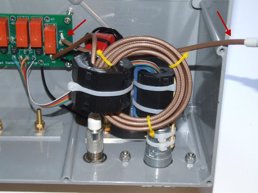
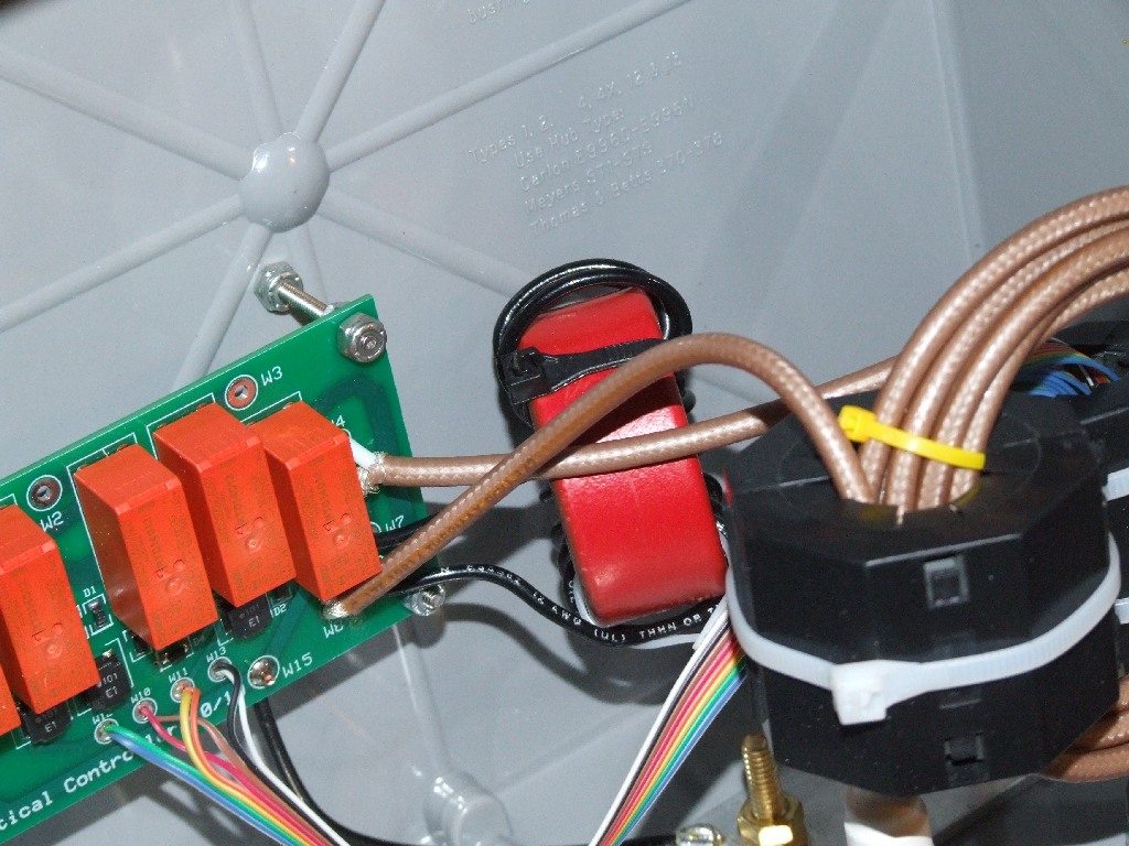
The transmission line choke is on the left. The RG-142 cable terminates on one end in a UHF plug that goes through a female to female feed through as it passes outside of the box. The other side of the transmission line is soldered directly to the PCB. I used an 8-wire ribbon cable for the control cable, using two physical wires as one signal wire. This choke is on the right, behind the transmission line coil. The control cable choke is physically supported by the control cable connector, which is a 6-wire connector used for automobile trailer wiring.
The location of the external connectors determined the location of the chokes. The connectors were placed on the bottom side of the box since the cables were coming up from the ground, and it's also the best side to repel and shed water. That then locates the chokes right above the connectors, literally supported by them. That then locates the PCB to the upper left of the chokes. It's one of those knee bone is connected to the shin bone kind of things.
Also visible in this picture are two aluminum bars that are part of the electrical ground and physical mounting scheme. The outside of the box sits on a piece of aluminum angle stock. That piece is clamped to the tower base and makes the electrical ground connection. The ground connection is brought up into the box using 4 brass screws. The brass screws go through two pieces of flat aluminum stock. These are mainly used to provide mechanical support for the box, since with them, the box wall is sandwiched between large pieces of aluminum. It was not possible to use a single piece of aluminum on the inside of the box due to the rib that divides each side, and provides the hole for a lid screw. From the brass screws, ring terminals and #12 insulated solid wire bring the ground to the PCB. Two ground wires run to the PCB.
I placed two red arrows that point at the cable for the dummy load. The UHF plug is just off the right side of the picture. It complicates the picture, and I wanted to call it out for the sharp reader.
Finally, if one were out to build a serious choke, using more than one core probably makes sense. The number of cores would also change the shape of the impedance curves. It all depends upon the power levels and amount of current flowing through the core. As I said earlier, in this case, I'm happy to view these are lightning loops as much as anything else.
The box interface to the outside world consists of:
Ceramic feed through for the antenna wire.
Aluminum mounting and grounding plate.
UHF connector.
Control cable connector.
Ceramic feed through insulators are normally used for high impedance and high voltage signals since they provide a high voltage barrier. In this case, I should be on the low impedance side, well under 50 Ohms. So, I don't really need the luxury of the insulator for the sake of voltage. But, I still need to penetrate the wall of the box. The box is otherwise water tight, so I don't want some sort of sloppy hole. Given the voltage levels, I probably could have just drilled a hole and passed a #12 insulated wire through it. That would qualify as sloppy. I wanted a ceramic insulator to provide a quality transition out of the box with a primary concern for being water tight. Having a nice mounting stud at the back and inside of the box is also important.
Here is a picture of the bottom of the box showing the other connections.
|
|
|
Control Box Bottom |
The aluminum angle stock carries electrical ground into the box via the 4 brass screws. It is also the surface that the box rests on. Two holes can be seen on the front face for bolts that hold the angle up against the radial grounding stock on the base. The RF interface is a female to female bulkhead UHF connector, and the control cable comes in through a 6-pin trailer connector with a spring loaded cover.
The contents of the box are now coming into focus. They include:
Control PCB.
RF Choke for the transmission line.
RF Choke for the control cable
UHF and control cable panel connectors.
Matching inductor.
Shift Down inductor.
Dummy load.
Feed through for the antenna wire.
It ends up being a pretty large box. What I've used in the past are boxes made by Carlon, and available from the Home Depot, if not many other places. They are a decent quality plastic, and have a flexible gasket on the lid to make it water tight. They are designed for outdoor service. This is the box that measures approximately 12" X 12" X 7", and costs around $30 in the 2010 time frame. I used this same box on my Hex Array, and I can tell you that they once were cheaper!
At the time I wrote this page, I did not have the dummy load installed. The load that will be installed is the 1500 watt Vectronics DL-650M. Although carrying a 1500 watt label, that is only for a short time duration. For this project, its main desirable attribute is the size, which is approximately 3" X 3" X 9". That fits perfectly into the top section of the box. When you see pictures of the box on this page, just imagine that dummy load installed on the top, above the PCB. While I might tune up into this dummy load, I do have other loads available. What it's really there for is as a safety backup to protect the transmitter if the control box should lose power while transmitting. Yes, the chances of that are low, but if I'm so paranoid about lightning, just imagine what else keeps me awake at night!
Here is a picture of the inside of the box, with all contents except the dummy load.
|
|
|
Control Box Guts |
The dummy load space is shown at the top. The orange arrow indicates the UHF plug for the dummy load. The red arrow points at the connection to the ceramic feed through. The green arrow indicates the shift down inductor. This is a small inductor that drops the resonance of the vertical to give me a second SWR dip. It is described on the Models and Measurements page. Because it is very small, I made it from 3 turns of #12 insulated wire, wound on some form that I can't even remember. In any case, the form was remove, and the coil just hangs in the air, supported by the wire connections to the PCB. The blue arrow points at the matching coil, which is behind the chokes. That coil, also described on the other page, is wound on a T225A-2 powered iron core, since the inductance is higher 2.83 uH. Here is a better picture of that inductor.
|
|
|
Matching Inductor |
The matching inductor is supported by its wire, which is #12 solid. What was nice about the box is that it was so big that I could put parts in front of and behind others, as well as next to each other.
A lot of time was spent thinking about how the box would mount on the vertical base, and how it would interact with the vertical as it tilts down. I must admit that I lucked out in that regard, since the vertical can tilt down and straddle the box without problems. I would need to disconnect the antenna wire on the rear of the feed through, however. Here is a picture of the box mounted and in service on the vertical base. Please click on the picture for a larger size.
|
|
|
Control Box on Base |
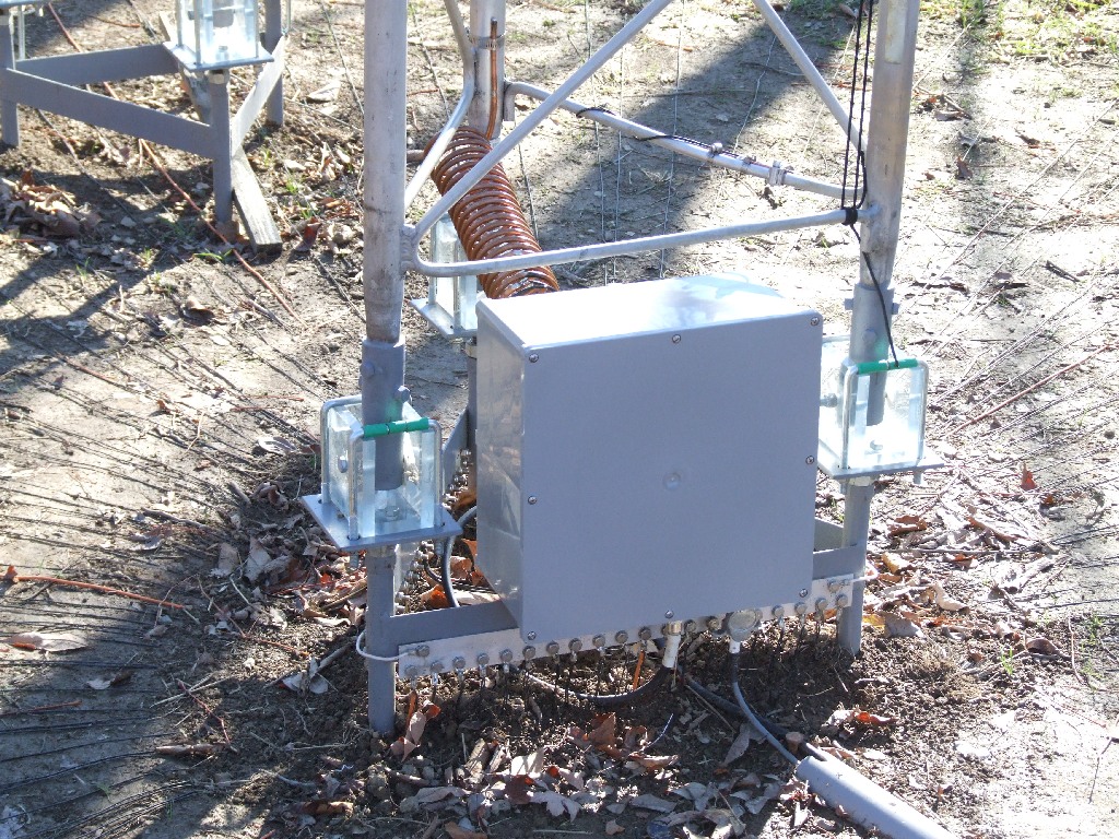
Many of the radial wires are visible on the ground, all 120 of them. The aluminum angle bolted to the bottom of the box sits on the steel band that rings the triangular base. The angle also overlaps the top of the aluminum ground bar that accepts the radial wire bolts. This overlap is around 8 inches long, and hopefully provides a very good low impedance ground path into the box. The box is held against the base with two brass bolts. The nuts on the bolts must be tight to have a good ground connection. To remove the box, the two wing nuts on the bolts are removed, along with the coax cable connector, control wire connector, and the antenna wire, which is on the rear of the box. The box is then free, and can be brought inside for service.
The tower tilts towards the viewer, and the lower aluminum strut clears the front of the box. So, the tower can be tilted up and down with the box in place. In this picture, all of the hinge U bolts are installed. As long as we are sharing pictures, here's one of the back of the box.
|
|
|
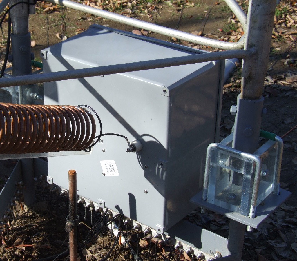
Control Box Back |
This shows how the base loading coil travels from the far tower leg towards the box, terminating on a ring terminal that connects to the ceramic feed through. Many thanks to K8AZ for the donation of the feed through to this project. It was the one part that was otherwise not in my junk box and difficult to acquire.
Here's a section that means absolutely nothing to anybody but me. It's the map of how the wires go from the radio to the control box. They pass through several connectors and boxes, and the colors need to be kept straight.
This is the wire routing for the control signals. 4 wires are needed:
GND
UnShort (12 VDC, 66 mA)
Online (12 VDC, 99 mA)
ShiftDown (12 VDC, 66 mA)
The Online signal also activates the Unshort signal via a diode
bridge on the PCB. Without that bridge, the current would be 33 mA (a single
relay).
In the house, the 4 wires are on the rotator control cable that runs to the
east. The other 4 wires drive the Hex Array.
The assignments are:
GND: Black
UnShort: Red
Online: Orange
ShiftDown: Blue
At the control box mounted next to the RCS-4, the 4 wires are connected to a 5-pin round trailer connector. These appear to be hard to find, and should probably be replaced with a 4 or 6 pin connector. The whole box needs to be replaced as well.
The 5 Pin connector has the following assigments:
Pin 1: GND
Pin 2: ShiftDown (Blue)
Pin 3: UnShort (Red)
Pin 4: Online (Orange (with Yellow Pigtail))
The connector has 4 pigtails on it that are joined to the cable
going into the house with wire nuts. I did not have orange wire, so, I used a
yellow pigtail that goes from the connector to the orange wire going back to the
house.
The 9 wire control cable that runs to the vertical has the
following signal assignments. With the idea in mind that there will never be
more than 6 signal wires, 3 of the signals are "doubled up" on the cable.
Shield, Black: GND
Red, Red/Black stripe: ShiftDown
White, White/Black stripe: UnShort
Orange: Online
Green: Online
Blue: GND
At the vertical control box, the signals go through a 6-pin round trailer connector. The signal assignments are:
A = GND (Shield, Black)
S = ShiftDown (Red, Red/Black)
TM = UnShort (White, White/Black)
GD = Online (Green)
LT = Online (Orange)
RT = GND (Blue)
Inside the box, a ribbon cable is used to carry the signals from the trailer
connector to the PCB. An 8-wire cable is used, with two wires assigned to each
signal.
GND: Black/White - W13
ShiftDown: Red/Brown - W10
Online: Orange/Yellow - W11
UnShort: Blue/Green - W12
The PCB hole designations are listed on the right, for example, W13 is the hole
with the silkscreen label W13.
Back to the 2010 W8WWV Vertical Page
Back to my Experimentation Page