 |
| Vertical V1.0, October, 2010 (Wet Noodle 90) |
Introduction
Greg Ordy
It's hard to believe that I've held my amateur radio license for a little over 40 years. It all started off at age 15 in 1969. While I was quite active through high school and early college, the hobby got pushed to the back burner while many other interesting activities took over in my 20's and 30's. Right around the time I was turning 40, the itch returned, and I started to expand the minimal station that I always kept around and used from time to time. This was in the mid 1990's.
For some reason, I decided to try 160 meters. I was unable to get on this band in the past, mainly because I never had the space for any sort of decent antenna. Now, on 5 acres, space seemed endless. It never is, but at the time, it seemed infinite. I had already started to discover that verticals worked very well on the lower HF bands at my location, so the only long term solution I contemplated was a vertical for 160 meters. Let me mention that I do have more of a DX perspective as opposed to domestic ragchewing. I did put up a 160 meter dipole for a short amount of time, but there were several really bad ideas associated with that project. Remind me to never think of that experience again.
I ended up erecting a vertical that was center loaded and approximately 70 feet tall. The bottom half was a wooden frame, and the top half was aluminum tube around 1 inch in diameter. A number of ground radials were laid out that were around 60 feet long. The exact number escapes me today, but it probably was close to 32. I thought that the antenna worked very well. I remember one African DXpedition that worked something like only 9 USA stations on 160 meters, and I was one of them. So, I thought I was doing OK. I soon discovered that the antenna, which was great for transmitting, was very noisy on reception. That led to years and years of experimenting with various receiving antennas.
There really was nothing wrong with the vertical antenna itself. It stood tall and a little bowed until the day it was taken down, in the summer of 2010. The problem areas were in the surrounding grounds, the radial system, and some lightning damage.
The antenna was tucked away in a corner of the property that was rather wild and untamed. It was field mixed in with a lot of crab apple trees and other random trees. By field, I really mean waist high weeds that were hard to work in once fully grown in the summer. I was ambitious enough to install the antenna and radials initially, but then nature soon took over and embraced the wires as her own. Since there were wires on the ground, bringing in machines other than a grass cutter was now undesirable. I went through a period where I was erecting a lot of verticals for various bands. I found that a good source of radial wire was bare electric fence wire. At the time, you could pick up something like a quarter mile of wire for seven dollars at the local farm supply store. It was cheap and worked well, although it contained steel and was therefore ferrous (magnetic). Boy could I lay out radials fast and furious. I would sink in a ground rod at the vertical base, and then wrap a radial wire around the rod and run it out to a wooden stake. I would do two radials with one wire run (opposite directions). When done, a torch was used to solder all of the radials to the ground rod. Since I usually changed or replaced an antenna after a year or two of experimentation, I never really noticed that the radial wire I used was not a good long term solution. When left on the ground for several years, as in the case of the 160 meter vertical here, the wires seemed to just slowly disappear. I don't mean bury itself in the ground, although that happened too. I mean corrode away. Fence wire is fine in the air, but apparently touching the ground creates some sort of undesirable chemical reaction in addition to oxidation. The final death was due to a lightning strike. That damaged the vertical base control relay, the transmission line, and seemed to make large sections of radial wire just disappear into the cosmic void. The vertical itself was undamaged.
So, I ended up with a perfectly good vertical that was located in a difficult part of the property with a defective transmission line and radial system. Some amount of the transmission line and radials were buried, some was vaporized, corroded, or otherwise damaged.
Thought was given to replacing everything but the vertical. There is nothing wrong with that approach. I guess that I opted for replacing everything, mainly in the name of trying to improve all aspects of the antenna system. What really interested me was trying to get to a full quarter wavelength up in the air, not only for a little additional gain, but mainly for increased bandwidth.
These pages describe what I ended up building. The new vertical became operational in October of 2010. It's still not really complete in that I was unable to get to the full quarter wavelength with the first version. With winter closing in on the northern hemisphere, that will be a project for a future season. I've learned that it makes sense for me to document on web pages what I do at my station, since I tend to find reasons to reference it in the future. It's amazing how quickly the memory fades as the years go by. If I just jot down some notes and toss them into a drawer, I never do a good job of capturing it all. So, here are my notes. Perhaps you'll find some useful ideas in this information, or, have some improvements to suggest to me.
I do have several other pages that relate to the original vertical. In particular:
Building High Power, High Q, Loading Coils: A look at the center loading coil when the old vertical was first installed.
Building High Power, High Q, Loading Coils - Epilogue: A look at the center loading coil after it was removed from the antenna earlier this summer.
Lightning Strikes!: A page describing the lightning damage.
While working on the vertical project I had to check out the (different) transmission line that I planned on reusing. That work is described on the LDF4-50A and L44PW page.
Here is a picture of what I might call V1.0 of the vertical. This is the October, 2010 configuration, which will probably be used until next spring, since winter around here is no fun for antenna work. Please click on the picture for a larger view.
|
|
| Vertical V1.0, October, 2010 (Wet Noodle 90) |
The bottom part of the antenna is not visible. The lowest set of three guy ropes is at the 50 foot level, which is at the top of the tower. The next set of guy ropes is at the 70 foot level, half way up the whip. The last set is at the top of the whip, at 90 feet. Those guys start off as 20 feet of wire, providing top loading. This is described on the Models and Measurements page.
It's time for a safety disclaimer. This set of web pages is going to describe two aluminum antenna towers that form a 160 meter vertical and a companion raising fixture. In my mind, these are antennas, not towers, and will never be climbed by me or anybody. I used a mixture of computations, experience, and common sense to arrive at the many engineering decisions. I never took into account the idea of a person climbing either tower because it will never happen. That gave me complete freedom to be competent, but not perfect. If you erect a tower that will be climbed by a human being you must follow all rules and codes and laws, and take every possible step to make sure that a person or substantial property is never injured or damaged. My antenna sits far from all other objects, and if it collapses very little can be damaged. Please do not think that any of the decisions I describe are based upon what is needed to allow humans to climb either tower - they never were. If your antenna projects have any chance of hurting people or property, take all necessary precautions. Living with regret is no fun.
Over the years I had the chance to make a long wish list for this antenna. The items on the list included:
Full size 1/4 wavelength long. Get rid of the need for loading devices. In the end, I had to back off on the goal for the first version, but it's a guaranteed way to get good performance and a wide bandwidth. My first version is 90 feet tall, with top loading and bottom loading to achieve resonance.
Between 60 and 120 ground mounted radials. In recent years many different studies and measurements have shown that the additional gain above 32 radials is small (assuming they are not too short). That doesn't mean you don't go after it! On top of that, radial wires do break or malfunction over time. If you start with 120 radials, you might have 80 in 5 years. Having a lot to begin with is a good way to make sure you always have enough. I was able to install 120 radials, with lengths ranging from a low of 60 feet to a maximum of around 110 feet.
Tilt over construction with the ability to raise and lower the antenna with one or two people. I used this approach with my 80/40 meter Hex Array, and it has worked out well. Given the length of a 160 meter 1/4 wavelength vertical, this strongly suggested that the vertical be made from an aluminum tower. Steel towers are just plain heavy and can rust. Aluminum is more conductive than steel. Both the antenna and the raising fixture are made from aluminum tower sections.
No climbing!
No concrete. Concrete is not needed for the base if it's a light weight aluminum tower with a companion raising fixture. The base is just a place to pin the vertical to the ground with a hinge.
The ability to easily and quickly cut the grass around the antenna without damage to the transmission line and control cable or the radial wires. Perhaps the biggest mistake I made with my six element vertical array was to have lines running on the ground. The radials all nicely buried themselves over the years, but I have 6 antenna cables and a large control cable that are located on top of the ground. Every time I want to cut the grass in that area, I have to take up the lines, cut, and then put them back. The time waste over the years is large.
An insulated base so that the antenna can be easily floated or grounded. The insulated base is also the hinge mechanism, and is made from polycarbonate (Lexan). No shunt feeding. Floating or grounding the antenna is desirable so that the antenna can be made electrically invisible on different bands. I also had a concern about lightning damage, since it happened in the past, and this is going to be the tallest structure in the area.
If it's not clear from my various points, I've decided that it's important to me that the entire antenna system be located over what amounts to a normal lawn area. This is all based upon maintenance and upgrade considerations. I started off with 5 acres of mainly weed fields, and carved out 1 acre for the house and yard. That was over 20 years ago. Now, it's almost all yard, mainly due to antennas, although I must confess that open fields full of weeds are not that pretty if you are too close to them. It is easy to cut a path into a field, drive a support pipe for a vertical, run some radials, and get on the air. I did that for several years, and since I wanted to change the antennas frequently, it was not too bad. But once things start to become a bit more permanent, waist high weeds are a real problem. After just a season, a coaxial cable will work its way down to the ground between the weeds. If you want to move it, it will be amazingly hard to move. Everything gets tangled with the weeds. If you drop a nut, bolt, or small part in a field, it can be impossible to find.
The good thing about weeds is that if you start mowing then frequently you will slowly turn the area into acceptable grass. It's not a beautiful city park, but the natural grasses are encouraged by the frequent cutting, and the taller weeds get the idea and move on to other places. Radials present their own problems. Where I live, they do tend to bury themselves right below the surface. This is great. They are out of sight, and protected from normal activities, and you can't trip over them or damage them. But, what if you want to do more serious landscaping in the area? Now, they are in the way for any operation that needs to break the ground surface, such as tilling, planting trees, or grading. With radials that are around 100 feet long, a 160 meter vertical covers nearly an acre of land. The implication for me was that I needed to make sure that the entire acre was how I wanted it to be for the next 20 years because once I put down the radials, I really didn't want to disturb the ground, even in a small area. It's foolish to think that I could get that 100% correct, but, you get the idea - first make the land the way you want it, and then lay the radials, hoping to never have to replace them.
So, the bottom line is that of the work and time spent on this project, probably 95% or more of it was spent on preparing the area. I spent serious time over two years with my tractor and chain saw getting the area thinned, graded, and cleaned up. This includes removing rocks and stumps and ridding the area of poison ivy and lots of nasty thorny bushes. Now I said thinned, not cleared. Clearing would have been much easier, and better if the only consideration was antennas. My overall area is already open enough. I wanted as many trees in the antenna region as possible. They are desirable for lots of reasons. If nothing else, I think about the next owner of the house. Since they were all naturally planted, however, their locations were often a problem. The number one rule was that I needed to make sure that I could cut all of the area with my mower, which is around 6 feet wide. So, trees can't form little zones where you can't get in to the ground around them. I guess that another way to express my goal is to say that I wanted to create an acre of natural beauty that could be easily maintained, and somehow managed to have a 160 meter vertical dropped in the middle. Good luck!
I can appreciate that if you started off reading this page to see what I was doing with a vertical and ended up on a landscaping page you might feel cheated. So, let's get back on topic. I did want to make it clear, however, that from my perspective, the work and sweat of this project was all about preparing the land for the vertical. That went on for years. The vertical went up in days and weeks. The initial emphasis on landscaping is due to ground radials creating a situation where you just want to leave the ground alone in the future, other than to cut the grass. Still, from where I sit, one of the most important antenna tools is this, my old Kubota B7200 tractor, and set of 3-point hitch attachments. Rakes, tillers, scrapers, the whole shooting match. More than just radios are made in Japan.
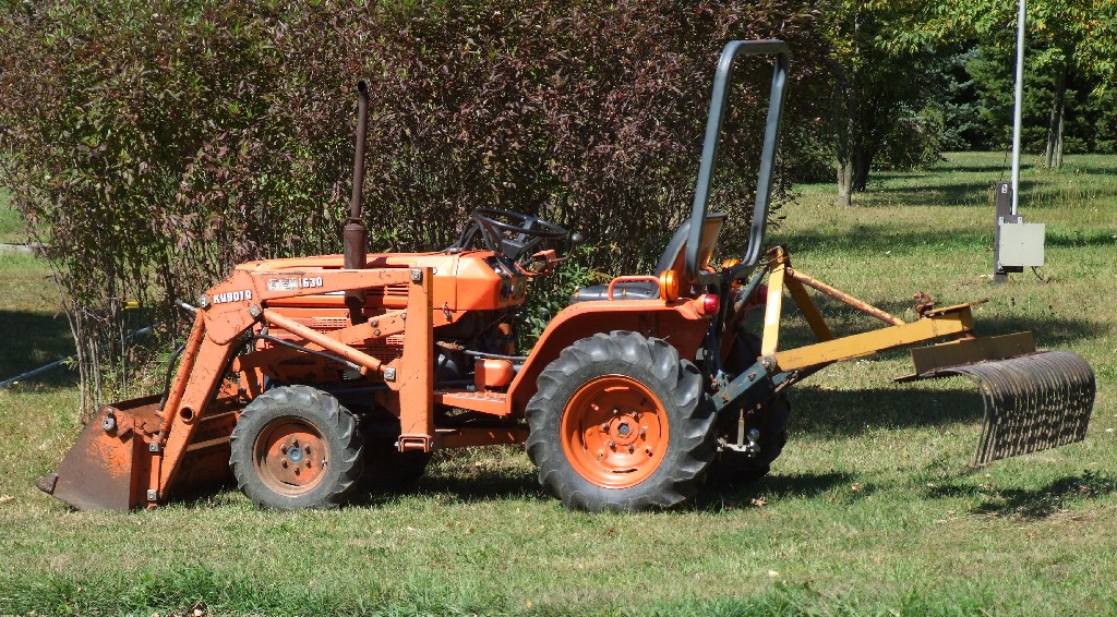 |
| Kubota B7200 |
The details of the vertical are captured on 3 web pages. They are:
Vertical Construction: Describes the Vertical, radial mounting system, base, and hinges.
Control Box: Describes the box at the base of the vertical that holds a PCB with relays for switching various configuration.
Models and Measurements: Looks at the models I used to help size inductors and loading wires, and measurements of the actual vertical.
2011 Update: How the vertical performed and survived over its first winter.
I suspect that we have all discovered the various aerial picture and mapping sites that provide views of most populated areas. I wanted to finish this page with some pictures from maps.google.com of the vertical site. From looking at the pictures in detail, I can tell that the current picture was taken just months (around May/June 2010) before the vertical was erected. The timing is determined from the state of various piles of cut trees and bushes that had or had not been burned. I guess that's like investigating an ancient culture by going through their garbage dump. Sooner or later there will be a picture after the vertical is erected, and that should show quite a difference, after the final landscaping, grading, and laying of the ground radial field. Of course if the next picture is taken far enough into the future, the site will tend to look like it did before, as everything all continues to grow, especially the grass. At the time of laying the radials, the ground in the area was reduced to dirt.
Here is a picture of the overall property. As with most all of my pictures, you can click on them to enlarge them.
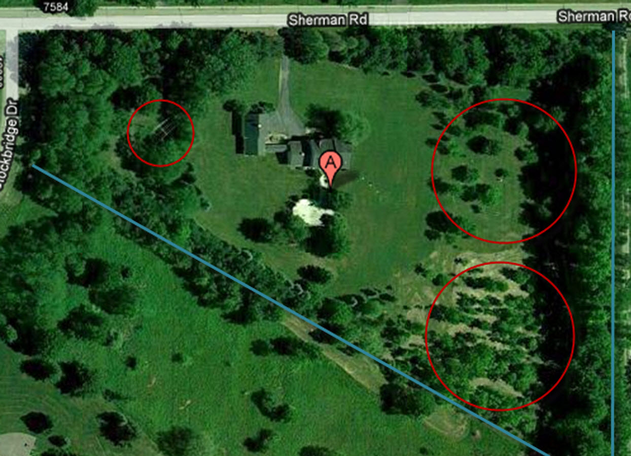 |
| W8WWV Site |
The blue lines, along with the two roads, set the property boundaries. Yes, I live on a strange shaped lot that is like a triangle with a corner that is a little bit clipped off. The left side red circle is drawn around the tower that holds my Sommer Yagi antenna, and also an 80 meter invered vee. The right circle on the top is drawn around the Hex Array, which is a 6 element vertical array for 80 and 40 meters. Finally, the lower right circle is drawn around the location of the 160 meter vertical. Earlier, I said that it was tucked away, well, because it is placed into the corner of the triangle. Other little receiving antennas are too small to be seen.
For future reference, here is a closer picture of the vertical area.
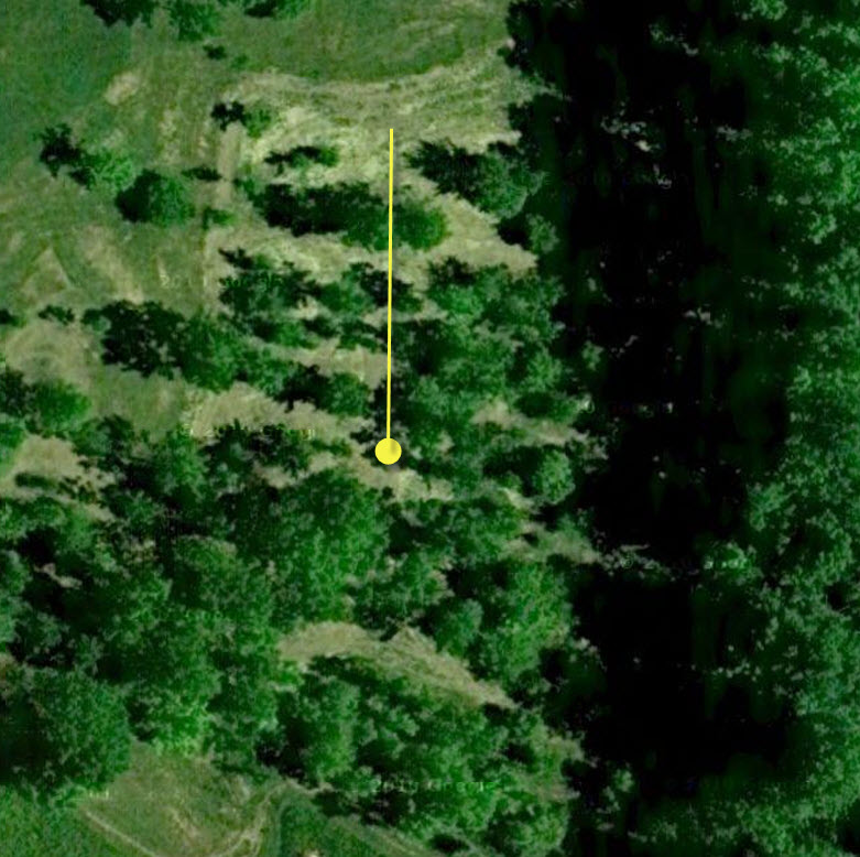 |
| 160 Meter Vertical Site |
The yellow circle marks the location of the base of the vertical, and the yellow line is the position and length of the vertical when it is tilted over to the ground. I know that it looks as if the vertical is in the midst of many trees. It's not really that dense. The shadows in this picture tend to make every tree appear about twice as large as they really are, and, this was taken before the final clearing of this year (2010). There is a nice and straight alley that runs through the trees which is where the vertical tilts down to the ground. It's probably the only long and straight path in the area, but I only need one.
Back to my Experimentation Page