 |
| RCS-4 Charred Coax Connector (going to 160 Meter Vertical) |
Greg Ordy
I live in a part of the country (northern Ohio, United States) where lightning is not much of a problem. We do have strong late spring and early summer thunderstorms, but nothing like I hear about in places such as Florida, that have a very serious lightning problem. My antennas are near trees that are as tall as my tower, or tallest vertical. If you travel about 1000 feet up the road, there is a hill which is about 100 feet high. I don't want to give the impression that I live in a valley, far from it. But, I don't live at the top of a hill either. My antennas don't stick out. If you travel about a mile more in that direction, you will get to the house of another ham. His location sits about 100 feet higher than mine, and he has a 150 foot tall tower, whereas my tallest antenna is approximately 70 feet tall. You can see his tower in certain directions for many miles. I've also helped him twice take down rotators damaged by lightning strikes. So, the potential is there for damage, but where I am, it's not been much of a problem - knock on wood.
Still, this doesn't mean that I ignore lightning. If anything, I've tried to implement a conservative amount of lightning suppression and protection. My tower has two 8 foot copper-clad steel rods at the base, and has lightning protection for both the rotator control cable, as well as the transmission line. The lines run underground to the house, a distance of approximately 150 feet. My verticals are all located over large ground radial systems, that include ground rods at the center. The 160 meter vertical is at DC ground, through an inductor at the feed point that provides a 50 Ohm match. The verticals go through a remote coax switch, and then the transmission line and control cables travel underground to the house. At the outside of the house, there are more lightning suppressors and ground rods. Inside the station, I have a copper bar strapped to the back of the desk that serves as a common ground for equipment. It's connected to the outside ground rods with a large diameter cable.
I don't disconnect my radio from the antennas when not operating - that would be work. I do try and remember to use my various coax switches to connect the radio to a dummy load when not in use.
To be honest about it, I figure that some amount of damage from time to time due to lightning is inevitable. My main goal has been to keep the house from catching on fire. I can replace my ham radio station, I just don't want to have to replace the house!
In the last week of May, 2006, we had some very serious thunderstorms. This was part of the endless rain that went on to flood many parts of eastern states, such as Pennsylvania and New Jersey. We escaped the floods, but not the storms. It was late afternoon, and I was sitting in my office chair. When in that chair, I naturally look out towards my 160 meter vertical, which is several hundred feet away. A bright lightning bolt lit up the afternoon sky, and it was in the direction of the vertical. The time gap between the lightning and thunder was very short, so I knew that the strike was close. The rule of thumb is that there is one mile of distance to the strike for every 5 second period between seeing the bolt, and hearing the clap. This wasn't a direct hit, just a nearby strike.
I'm most concerned about the microprocessor controller that is part of my Hex Array. Seems to me that it is the most vulnerable piece of outside equipment. I have had RS-232 driver chips fail due to lightning before, but they were added to act ask a form of protection, so their destruction is not unexpected. This strike, however, was so intense, that I expected more problems. As it turned out, a number of parts were damaged. The total repair bill was approximately $200. This page details the damage, and some of the decisions that were part of the rebuilding process.
One of the most respected and well-known sources of lightning protection information and products is PolyPhaser. They have a number of informative web pages, as well as a specific amateur radio page. I use a number of PolyPhaser products here, and they all seem to be well constructed, and work as advertised.
The August, 2006 issue of QST has an article on station grounds that includes a discussion about lightning protection. The article is on page 48, and is written by the technical editor, John Hallas, W1ZR.
As best as I can tell, the lightning energy entered my system via my 160 meter vertical. I say this because I happened to witness the lightning bolt strike closest to that antenna. The relay at the base of the vertical that changes the resonance point was damaged, as were all of the coax connectors going back to the Ameritron RCS-4 remote coax switch. The switch itself was damaged, with fused relay contacts, and vaporized PCB traces. At that point, I believe that energy flowed out to the 80/40 meter Hex Array, connected to the same coax switch, where it damaged the RS-232 interface chips, and the microprocessor. The energy got onto the control signals going back to the house. At the house, the RS-232 interface chip was damaged, as well the serial port on the computer connected to the interface. It is also possible that lightning energy entered the Hex Array via its six vertical elements.
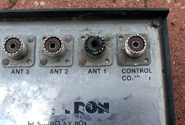
The tip off that the 160 meter vertical was the source of the energy surge was the state of the coax connector on the RCS-4 remote coax switch. Here is a picture of the RCS-4.
|
|
| RCS-4 Charred Coax Connector (going to 160 Meter Vertical) |
ANT 1 was connected to the 160 meter vertical. The coax connector was heavily charred. Upon opening the box, I found additional damage, which is described in the next section. All of the coax connections going back to the vertical were also burned. Here is a picture showing some of the connectors.
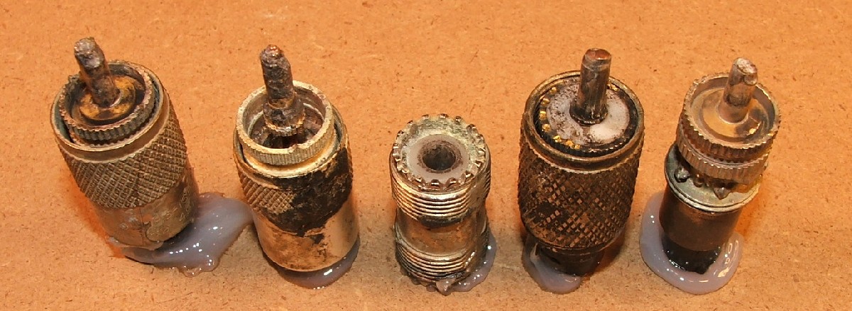 |
| Charred Coax Connectors |
The barrel connector is interesting in that the metal on one end of the center pin tunnel is gone.
In some cases, the nasty looking black charring can be cleaned off, and there is no real permanent damage. I tend to be conservative about this sort of thing, and replace all connectors that appear to have flashed over. So far in my amateur radio experiences, I have seen a number of connectors damaged by energy surges, but I have never seen coaxial cable itself damaged. Your mileage may vary.
The microprocessor in the Hex Array control box was damaged, and had to be replaced.
Finally, the last piece of damage was to a computer. The serial port that communicated with the Hex Array control microprocessor was blown out. In this case, I really mean blown out. When the board was removed from the PC, the RS-232 level conversion chip for the port had a piece missing - it was blown out of the plastic case. The board had 4 serial ports, fortunately I was only using 3. By changing the ribbon cables, I was able to use the previously unused port. Here is a picture of the damaged IC.
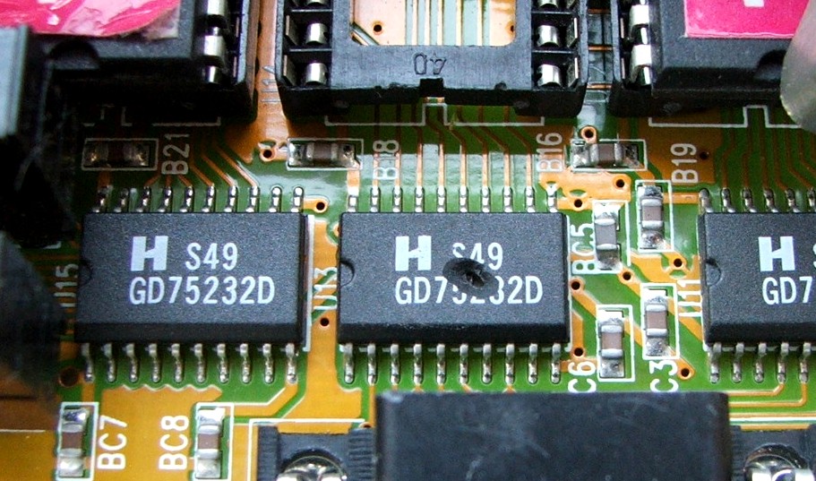 |
| Blown Out Serial Port RS-232 Level Conversion IC |
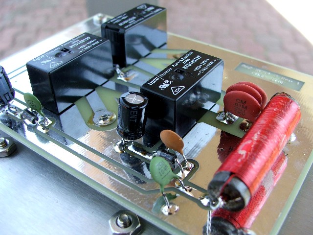
I have two Ameritron RCS-4 remote coax switches in my station, and until this incident, they worked without problem for a number of years. The RCS-4 instruction manual makes mention of lighting, and states that there are small air gaps on the PCB near each antenna connector to protect against lightning damage. In theory, the high energy of the lightning would be willing to jump the gap to ground, whereas normal amateur RF power levels would not notice the gaps. In my case, the lightning surge chose instead to vaporize three PCB traces, fuse together a set of relay contacts, and blow off the connection to a relay coil. Here is a picture of the PCB, with highlighting to show the vaporized traces, and circles to indicate the fused relay contacts and the blown coil wire. Please click on the picture for a larger view.
 |
| Damaged Ameritron RCS-4 |
It might seem as if this unit was shot, but in some ways, the damage was not too bad, and could be fixed.
Time to digress to some deep philosophy. Half my life ago, in my mid 20's, my attitude was that if most anything was broken with a piece of equipment, I was willing to replace it. If something lasted a few years, I though that I got good service out of it. Now, much older, it's amazing how cheap I am. If something doesn't last for at least 20 years, I'm starting to think it was a piece of junk. I'm always looking for ways to fix, and not replace. I'm always thinking in terms of maintenance.
The blown traces could be replaced with wire, and Ameritron was willing to sell me a replacement relay for $17 (USD). Of the three relays, the one with the fused contacts was the only one that appeared to be soldered to only the top side of the board. That would make replacement much easier than for the other two relays. It would also be desirable to replace the burned coax connector, shown in a previous picture.
The repair would take $17 in parts, and probably two hours of labor. My other alternative was to replace the relay box. Turns out that Ameritron was also willing to sell just the relay box (separate from the control box). They said that the current relay box would work with my older control box. The relay box cost $90.
So, do I repair or replace?
As so often happens, I was pretty much torn right down the middle. Neither course seemed to be the obviously better choice. Since Ameritron does update its designs from time to time, I decided to check their web site for documentation on the current RCS-4. I really like manufacturers who put their documentation on the Internet. Being able to go through manuals and check schematics before purchase is great. Ameritron is especially good in this regard.
After comparing the current RCS-4 relay box schematic to mine, it was clear that they had updated the relay box design. Here is a picture of my schematic, and then the current schematic. Please click on a schematic for a larger view.
 |
 |
| My RCS-4 Relay Box Schematic | Current RCS-4 Relay Box Schematic |
My first thought was that I glad to see that they reorganized the relay signal flow. In the older design, the ANT 4 port had to travel through all three relays to get out of the box. In the updated design, no signal had to go through more than two relays (in fact, all signals always go through two relays). Seems to me that the fewer the contacts, the better. Another issue that caught my eye was that in the older design, all of the transmission lines passed through one set of relay contacts on relay 1. The three relays were all DPDT, and relays 2 and 3 used both sets (poles) of contacts for RF. In the case of relay 1, only one pole carried RF, the other switched control signals. It turned out that the RF pole on relay 1 was the one that was fused by the energy surge! To me, this was the weak link in the design - transferring all RF energy through one pole of one relay. After viewing the two schematics, I decided to buy the newer control box, which I hoped was a more bullet-proof design.
When the new relay box arrived, I took it apart to see what was in there. The open frame relays of the earlier design were replaced with smaller encapsulated relays which I believe are generically called appliance relays, since they are often used in appliances (washers, dryers, refrigerators, etc). These relays have high current contacts, and work well with RF, so long as the frequency is kept relatively low.
Here is picture of the new RCS-4 relay control box.
 |
| New RCS-4 Relay Control Box |
The other design change involved the location of the coax connectors on the box. Here is a picture of both boxes, side-by-side.
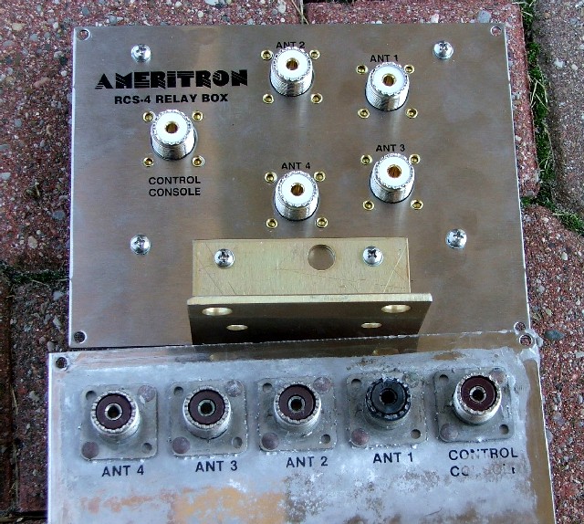 |
| Relay Box Coax Connector Comparison |
Although the layout has changed, it's hard to believe that this is a difference with a distinction.
With the RCS-4, ANT 4 is connected to the station coax when power is removed from the control box. In other words, when the internal relays are not energized, ANT 4 is connected to the station. If you are going to use a switch position to connect a dummy load, a good choice might be position 4. This would imply that if power was lost, as can happen during severe storms, the dummy load would be automatically connected to the radio. This could provide some added safety margin against lightning damage. If you don't have a dummy load on the switch, then the antenna least likely to sustain a strike could be connected to position 4.
RS-232 is the standard serial line (COM port) interface. It is used in this application to provide communication between the computer next to the radio, and the array controller. The choice of RS-232 on my part was mainly based upon convenience. I could have implemented any electrical signal level scheme, so long as the digital data traveled over it. If over time there are more problems, it may make sense to consider another choice, such as a current loop, driven with discrete transistors that can take a lot more abuse.
My computer is not connected directly to the cable going out to the array. An interface box sits in the middle, and it uses back to back RS-232 buffers to provide isolation for the computer. The RS-232 cable between the computer and the interface box is wrapped around a long ferrite rod. In the case of this strike, that protection was insufficient, since the computer RS-232 port was damaged.
To try and increase the safety margin in the future, I built up two small boxes, one for each side of the RS-232 cable. They contain filtering and protection circuits. I picked up some 35 volt MOVs at my local surplus electronics store, and these are used between ground and each data line and the power line. The data lines have 10 uH RF chokes in series, and a 0.01 uF capacitor in shunt. Those components form a low pass filter, designed to pass the low frequency data signal, and suppress everything else. Each box has an external stud and wing nut which is used to make a short connection to ground.
While I had similar filtering in the existing circuit, I must confess that my treatment of ground was a lot more casual. With these boxes, I'm using short and thick cables between the protection components and ground.
Here is a picture of one of the boxes.
 |
| New Lightning Protection Box |
Each box has the appropriate male and female connectors on each side. In other words, the box can be easily removed from the circuit. This is helpful for troubleshooting, since the box can be removed, and replaced with a direct connection, which helps isolate the location of any problems. As the picture shows, I've found that small cable ties and inexpensive grommets provide a functional strain relief mechanism. The grounding stud, which is a brass bolt, connects the terminal strips to the box, and in this view, comes out of the bottom of the box.
Philosophically, I'm trying to get less expensive and easy to replace parts to protect more expensive parts.
At some point, I'm going to add a lightning suppressor right at the base of the 160 meter vertical. Most all of my damage would have been eliminated if the energy surge would have stopped (directed to ground) at that point. Although the vertical is at DC ground, grounded by the impedance matching coil, it's clear that the energy surge found it easier to go down the coax as opposed to through the coil.
Back to my Experimentation Page