Vertical Construction
Greg Ordy
This page describes the construction and mechanical issues of the antenna towers, ground radial system, and then the lines and rigging that allow it to be raised and lowered, hinged on a tilt over base.
I had nothing but good experiences making the 6 verticals in the Hex Array tilt over. They were around 52 feet of aluminum tube with a bolt as a hinge pin mounted in a wooden base frame. A 20 foot long wooden raising fixture with a single backstay line held a pulley at the top that was used to raise and lower a vertical. It was fast and easy, and could be done with one person.
I had this vision of simply scaling it all up to 160 meters, with an antenna that was potentially 120 feet tall. I knew that the aluminum tube would need to be replaced with aluminum tower sections, and that the raising fixture would need to be as tall as possible. I started on a hunt for aluminum antenna towers. The major break occurred when I purchased a 50 foot tall Universal Tower from the estate of a ham who lived about 40 miles away. That was in the fall of 2008. The tower appears to be their model #5-50. I was also able to scrounge 30 feet of miscellaneous tower sections from neighborly hams. These sections were not all of the same family, but there was potential to make them work as the raising fixture. So, I had 50 feet of tower going towards the main vertical, and parts that could be combined to make a 30 foot tall second tower that would be the raising fixture. With the acquisition of more sections and some tubing for a whip at the top, getting to a full quarter wavelength on 160 meters looked possible. At least I had a good start.
Once I had the bottom sections for both towers, I could start to design a base and some hinges. The antenna is approximately 22" on a face, and the raising fixture is 18. Both structures need to tilt down to the ground, so I decided to treat them exactly the same, and use the same base and hinge design for both. The raising fixture does not need to be insulated, but I decided to use the same hinge just to keep it all the same and simple. Because the raising fixture is only 30 feet tall, it can be easily walked up with one person. Once up, it is guyed in four places with what I would call temporary guys. These are tied to small trees that are located in convenient spots.
If you have ever tried to walk up a hinged tower, you know there is this point in the process where the resistance force peaks. The exact location will be a function of the length and weight distribution, but it is in towards the hinge. The leverage creates what amounts to a nut cracker scenario, and the humans are the nuts. Using a raising fixture keeps the leverage from accumulating force near the hinge as there is a helping hand much further up the tower.
The basic idea is contained in this stick diagram. No expense was spared in creating these graphics.
|
|
| Basic Tower Schematic |
The red line is the antenna, and we want to tip it to the left on its hinged base. The blue raising fixture, standing close to the antenna, supports a pulley near the top. The green line goes from the antenna, over the pulley, and then down to the ground. It seems as if there are choices as to how the line makes its way to the ground. One popular option is to bring the green line right down the side of the raising fixture. I colored it orange to reduce the confusion. A winch is attached to the raising fixture at point A. While this configuration appears compact, you still need to counter the force of the main tower that wants to pull the raising fixture over to the left with it. A fixed line that counters the pull to the left is often called a backstay. If you located the winch at point A, you would certainly need a backstay line. An alternative to locating the winch at A is to locate it at B, which is, in effect, a combination backstay line and pulling line. I chose to locate my winch at point B. There is a variation on this idea where the raising fixture tips down to the ground as the main structure tips up. This is called the falling derrick method. Personally, it strikes me as very similar to putting the winch at point B.
When first installed, the pieces look like:
 |
| Lifting the Antenna |
As you stat to raise the antenna by pulling on the green line at point B, it's clear that the main forces on the antenna want to bend it over as opposed to collapse it down. Perhaps the most important advantage of using a tower as an antenna is that the lattice construction maximizes the strength and rigidity of the structure for the weight. In my case, however, I was only able to get my hands on 50 feet of tower for the first version. So, I decided to add aluminum tubing to the top as a way to get it as tall as I could. What I ended up with is what I might call the Wet Noodle 90, since it's 90 feet tall, and very flexible. Once vertical, it can be guyed in 3 places and is very solid. But, the problem is getting it vertical. I fully suspect that it could not support its own weight when tipped over (see the picture later on this page). Since the single pull line worked so well, I decided to add a second. The version 1.0 of the Wet Noodle 90 is rigged as follows:
 |
| Two Line Support |
The purple line supports the tubing that otherwise would bend and crumble. A second pulley was added to the top of the raising fixture for the purple rope. The rope can walk off of the top of the raising fixture pulley, which is necessary as the tower comes close to vertical, and we don't want to be pulling the top towards ground with the purple line. We always want to be pulling to keep the antenna from bending.
Now if this looks to be a bit more risky, it is. Two lines have to be pulled or released with a certain degree of synchronization. The goal is to keep the antenna straight as it is going up and down. At least two people are needed, but it works without much fuss or muss. In the future, I would like to add more tower sections, and shorten the tubing. This would lead to a rigid structure that would not need a two rope system.
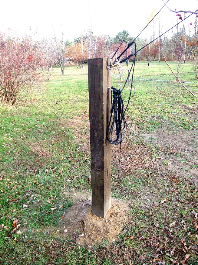
I was not interested in pouring concrete bases. I do have one for my tower that supports a Yagi, and putting in a concrete base is a lot of work and expense, no matter how small it might be. Given the light weight of the aluminum tower, and the fact that it would never be climbed by a person, a simple base sunk into the ground seemed more than adequate for my needs. On top of that, I need two bases, so, concrete would be really a big project if that meant two holes and pours. The usual rule in this part of the country, where we do have a lot of snow and cold temperatures, is to get down at least 2 to 3 feet which is below the frost line. The ground above the frost line is much more likely to heave and sink and shift. Obviously the deeper you go, the more stable and solid your base will be. My goal was to sink each base 3 feet into the ground.
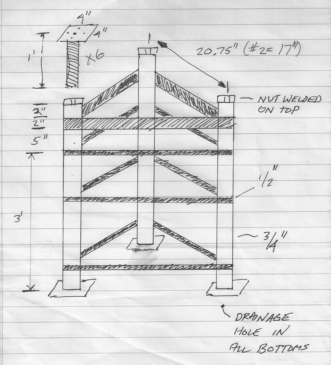
Seeing as we have a triangular tower with 3 legs, it's pretty clear that the base will also have 3 legs, and terminate in a pad that can hold the hinges. Those pads should have individually adjustable heights so that the tower can be made plumb. Pads are also needed on the bottom, and they will rest on brick blocks at the bottom of the hole. I picked 3/4" steel pipe for the legs. The top pads are welded to a foot of threaded 3/4" rod that screws into 3/4" nuts that are welded to the tops of the pipes. I added nuts to the threaded rod before I screwed the pads into the pipes. These were used to jam up against the welded nuts and hold the pads in place. 1/2" rebar was used to ring the pipes at three different heights. This locks the pipes in place, and provides a stable frame. The pads measure 5" X 5".
Near the top of the pipes, 1/8" flat steel stock that is 2" wide was welded around the pipes. This metal will support the aluminum radial wire mounting stock, and the control box.
These ideas led to the following sketch. I took it to my local welding shop - Chardon Welding. While they have done a few antenna projects for me over the years, I usually see them once or twice a year for tractor mending. It seems that if you use a tractor, you better find somebody who can weld - you'll need their services.
 |
| Tower Base Sketch |
The antenna tower base is 20.75" on center, and the raising fixture is 17". That is their only difference. The cost to fabricate both bases was around $350 in the summer of 2010. I painted the bases with several coats of rust resistant primer paint. The holes were dug by hand, using a post hole digger, spud bar, and shovel. What good exercise!
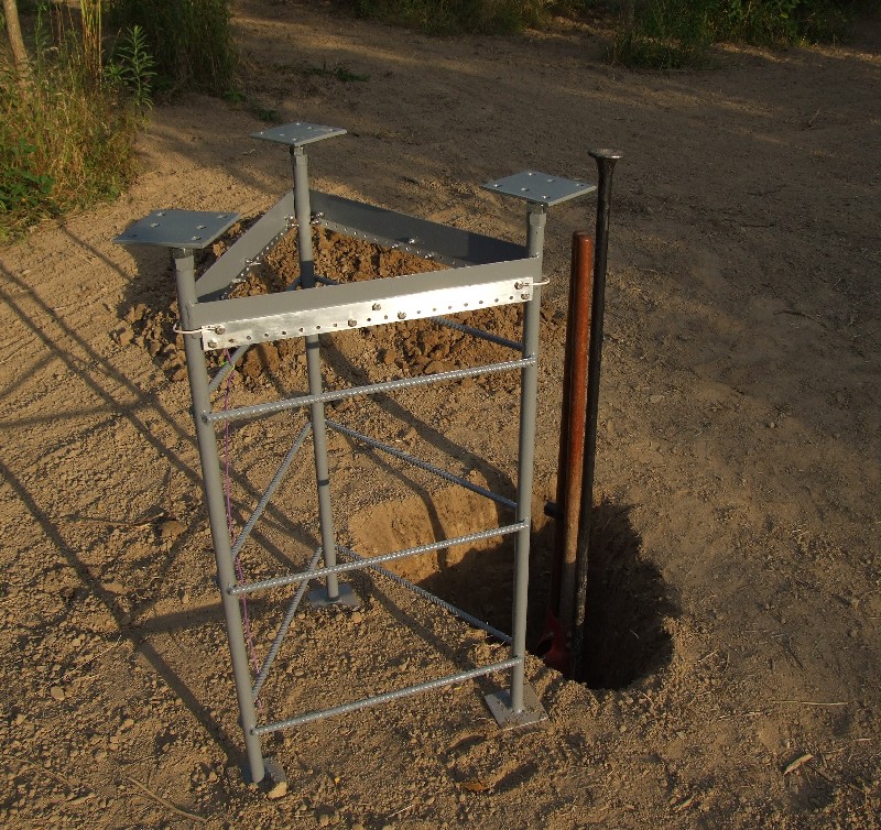
Here is a picture of the antenna base next to its hole as the hole was being dug.
 |
| Antenna Base Next to Hole |
The base is just about at the right depth in this next picture. The goal was to get the top piece of round rebar to be just a little below the natural grade. The radial lines attach to the aluminum bars, and then go under the top rebar and out.
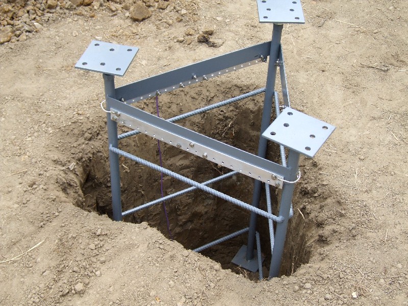 |
| Tower Base, Almost Ready |
Before I could fill the hole back in, I needed to bring in the lowest tower section and attach it to the base. It would act as a pointer, and tell me when the base had the desired orientation.
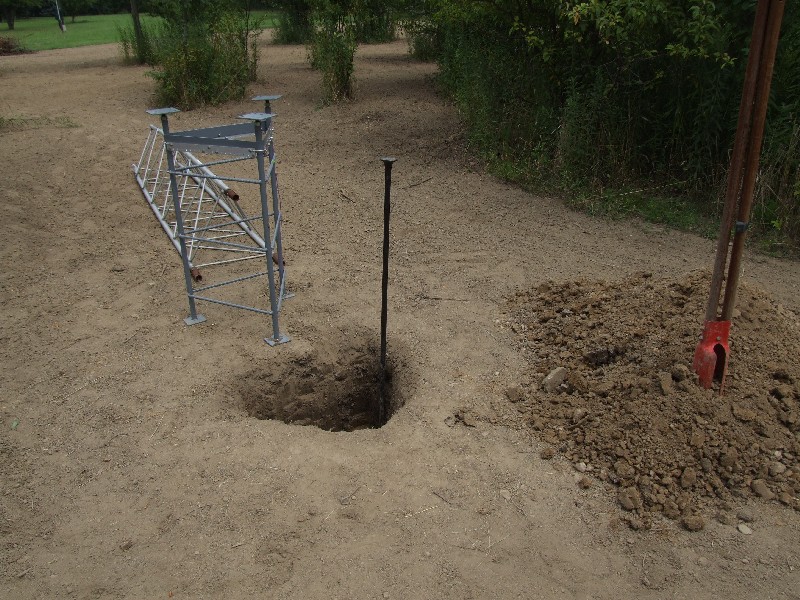 |
| Tower and Tower base are Almost Married |
The next picture shows the hinges on the base, and the tower on the hinges. I rotated the base left to right to get the tower in the exact right direction when on the ground. Certain trees and tree branches needed to be avoided. When the depth and orientation was correct, I back filled the hole. The bottom pads were resting on bricks, and I added some gravel to the bottom of the hole before dirt. Everybody always seems to add gravel, don't they?
 |
| Tower on the Base |
The reward for finishing the first base was to start the second. The raising fixture stands about 4 feet away from the antenna tower. The two tilt in opposite directions to stay out of each others way.
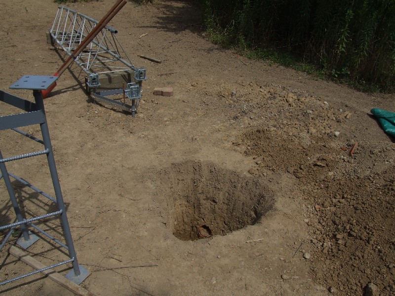 |
| Second Hole Started |
The hole pattern on the top pad marries up with the hinges, described in the next section. I expect the bases to settle over the first winter. I won't be surprised if come next spring I need to adjust the height of the top pads to keep the pads level and the towers plumb. That's the downside of not putting these bases in a big wad of concrete.
Both towers can tilt over, and that means hinges are needed. I also wanted an insulated antenna, so that suggested that the hinges also function as the insulators. The material that seemed to make the most sense was polycarbonate plastic, also know by the product name Lexan, although it is known by several names depending upon the maker. This is a very strong plastic, with good electrical properties, and reasonably good ultraviolet (sunlight) resistance properties. I designed a hinge out of 1/2" polycarbonate sheet, in the form of a "U" saddle hinge. 1/2" appeared to be the thickest sheet that was normally stocked where I shopped.
There is a store named the House of Plastics that is been in Cleveland for decades. Whenever I think of plastic, I think of them. I took my drawing down there and talked about it with one of the sales people, and I ended up in an email dialog with another. I was satisfied with their strength comments about the material. Given my informal drawing, they cut all of the pieces I needed, and the total cost was around $65, including a bottle of glue that was needed for the solvent welds.
The messy drawing that drove the hinge design looked like this:
 |
| Polycarbonate Hinge Drawing |
From an initial phone call with the House of Plastics, I knew that the 1/2" sheet cost $26.09 per square foot. The calculations at the bottom of the page suggested that I needed just about 2 square feet.
Each hinge consisted of two identical 4" X 4" side pieces, a bottom piece that acts more as a separator, since the sides are around it, not on top of it, and a rear stabilizer piece. In order to prevent hinge failure, the sides must remain vertical and not be able to tilt or collapse. The best way to support them, and also keep base metal from touching the tower legs, was to use a pair of square U bolts on the front and back of the hinge. The U bolt in the direction of the tilt would need to be removed for tilting, but otherwise could be left in place. The other U bolt is always installed. In fact, on the leg that is not part of the hinge, both U bolts can always be in place. When tilting, the leg drops down between the bolts.
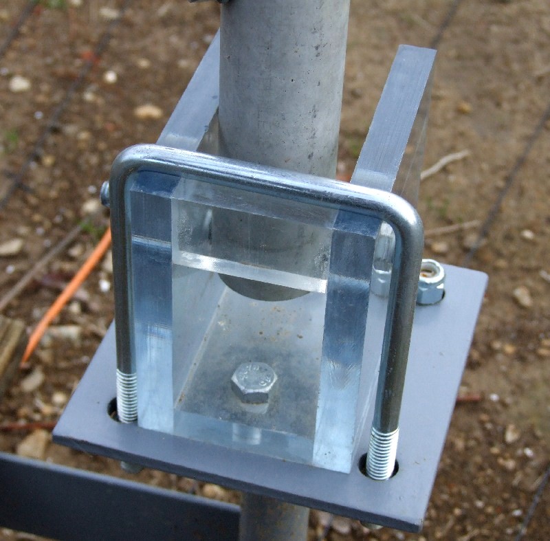
The first hinge picture is from a leg on the raising fixture tower. The square U bolt is on the left side of the hinge. The bottom separator piece has holes for two 3/8" bolts that pass through to the steel base plate. When I'm actively raising and lowering a tower, I tend to put the front U bolt in its holes, but pointing down and out of the way. This keeps it close so I don't find a way to lose it. The tower leg can then swing through the opening.
 |
| Polycarbonate Hinge |
The second picture shows the rear view of a hinge. The square U bolt keeps the plastic from twisting or racking. The hinge is held down with 6 bolts, the two in the base piece, and the 4 arms of the 2 U bolts.
 |
| Hinge Rear View |
The next hinge picture shows the antenna in the process of tilting.
 |
| Hinges in Operation |
The actual pins that the tower rests and hinges on are 3/8" bolts. Each bolt is supported beyond the tower leg by the 1/2" polycarbonate sheet, which transfers the weight down to the steel base pads. I really had no concern about the polycarbonate supporting the weight, since each of the 6 side pieces should be able to support hundreds and hundreds of pounds of weight. I doubt if the tower weights more than around 100 pounds, so the static weight (including the downward pull from the guy ropes) of the whole tower can probably be supported by 1 side piece, let along 6. But, I was concerned about the hinges while the tower was being tilted down and up. It's obviously a good idea to keep the tower from racking or wanting to come off axis. All I can say is that I've raised and lowered it several times, and the hinges have worked without problem, and show no signs of wear. Knock on plastic.
Finally, the raising fixture need not have insulated hinges. I used them there mainly to have a single solution for everything - all 6 legs. Electrically, insulating the base on the raising fixture should raise the first resonant frequency from where the length is 1/4 wavelength if grounded, to where it is 1/2 wavelength if open at the base. That effectively doubles the first frequency where the raising fixture should be a problem. Since it's around 30 feet long, that means the frequency where 30 feet is 1/2 wavelength. That's around 16 MHz. That's well above the antennas that are nearby, which should decrease the changes of undesirable coupling. Another way to look at it is that I have 3 spare hinges for the antenna stored on the raising fixture.
Ground radials can have a range of problems and challenges. What I was most interested in getting right were the connections at the base of the tower. Many different schemes have been used, described, and sold. I mentioned on the introduction page that for a fast installation I would drive in a ground rod, and simply wrap bare radial wire around the rod, and when done, use a gas torch to heat up the whole wad of wire and rod and let a lot of solder get sucked into the lump. Maintenance is not very easy since all of the wires make a big knob of confused metal, and the wire is usually a few inches off of the ground, so that it can be too easy to snag a radial near the rod. On my Hex Array, I made up circular copper tubes that went around the base of each vertical, and I soldered the radial wires to the tube ring. The ring had three vertical feet made from more tube that plunged into the ground. After all of the radials were soldered to the ring, and coated with liquid electrical tape, the ring was pushed flush down to the ground. There are several commercial solutions that provide a round plate with either a center hole for a pipe, or even a square hole for a 4" X 4" wooden post. These plates have screws around the perimeter that make the connections to the wires. I liked the idea of the screws and ring terminals from the standpoint of maintenance and replacement, but I didn't like them in constant contact with the ground. Since I had a 22" triangular tower as an antenna, I was not going to make a flat plate that went around that base!
One of the questions that needs to be asked at some point is how many radials will be used? I knew that I wanted at least 60, but that magic number 120 was also attractive, mainly to say that I had done it at least once. With a triangular tower, about 22 inches on a face, each face needed to be able to attach 20 or 40 of the total radials. That's about 1 inch spacing between attachment points, putting two radials on one ring terminal if 120 radials are used.
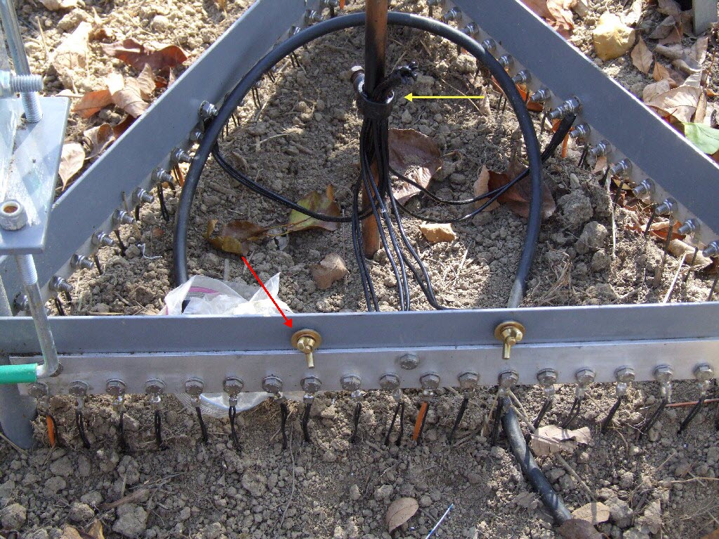
After some head scratching, I came up with the following scheme. Each tower face would have mounted on it a strip of aluminum bar that was drilled every inch with 20 holes for radials. On the ends of the bar, additional holes would be used to jumper around the triangle from face to face. Although the aluminum bar would be bolted to the steel base, I really didn't want to rely upon the base for electrical ground, since it will rust over time. Here is a picture of the aluminum bars making a ring around the triangular base, attached to the steel skirt.
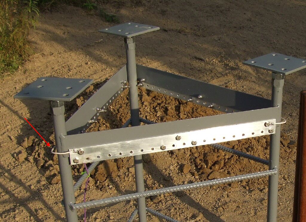 |
| Ground Radial Skirt |
I highlighted (red arrow) one of the ground straps that help insure a good electrical connection around the three corners, bonding the aluminum together. I used 1/4" stainless steel hardware for all of the connections to the ground bars.
To make maintenance easier, the bolts holding the ground wire ring terminals are located a few inches off of the ground. This also keeps them out of constant contact with the often wet ground. But, I now have to worry about how the wires run away from the skirt. If I immediately start running them away from the base, there will be a sharp 90 degree bend in the wire at the crimped and soldered ring terminal, and, the wire will be off of the ground, creating a tripping and snagging problem.
The solution was to exploit the round rebar down a few inches from the skirt. The radial wires would drop straight down from the bolts, and then go under the bar and out and away from the base. This keeps the wire running straight away from the ring terminal. The finished elevation of the rebar is right at the ground grade, so the wires are encouraged to be slightly below grade, while also being attached at a slightly elevated point.
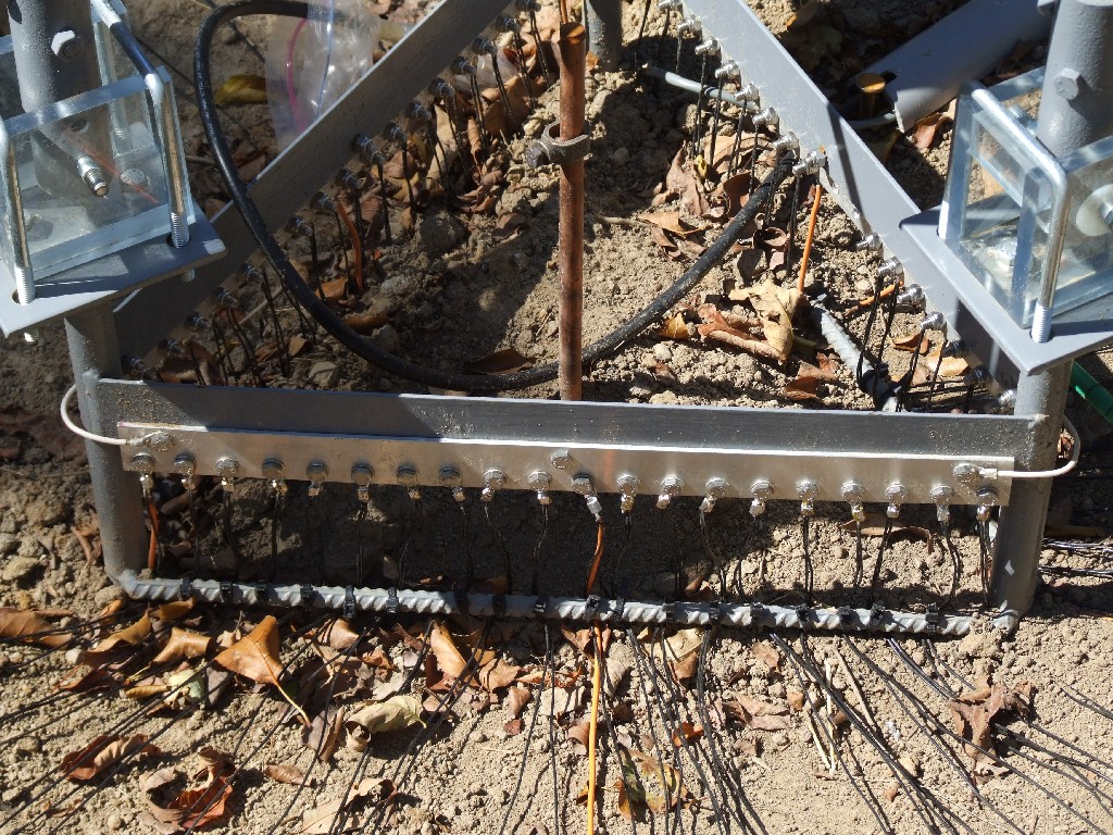
Here is a picture of the first few radial pairs after installation.
 |
| Radial Wire Pairs |
I used insulated and stranded appliance wire for the radial wire. A solid wire would probably be electrically a little better, but the appliance wire is very strong, and it will take a lot of abuse. I also have several miles of it in the cabinet. To help with keeping the installation process clear and orderly, I used an orange jacket for six of the radials. They are the wires off of the middle and ends of the faces. In other words, every 10 of the 60 holes. The wire gauge is #20, and the orange wire is #14. The gauge of radial wire is usually never a problem, since the return current is divided between a large number of wires. The strength and mechanical considerations are probably more important than the current capacity ones.
During installation, I removed the dirt from directly under the rebar, to make it easier to bring in the wire. I did end up with 120 radials, so each ring terminal attaches to 2 radial wires. I also found it helpful to strap the wire to the rebar with a cable tie. Without it, the wires would tend to be pulled to the side as you approach an end of a face. The cable ties also act as a strain relief. When the radials were all installed, I put the dirt back over the rebar.
Here is a picture of the base with all 120 wires and 60 ring terminals and nuts and bolts installed.
 |
| Radial Wires Installed |
This picture introduces another part of the ground system - an 8 foot 5/8" diameter copper clad over steel ground rod driven into the exact center of the tower triangle. This is designed to help lightning surges find their way to Mother Earth. For a tower of this height in this area, having more than one ground rod would probably be an improvement. But, I installed only one inside the base to keep the top out of the way of walking and mowing.
I installed the radial wires in pairs, where both were attached to the same ring terminal. To make it an easier one man job, I set up a wire dispenser out at the ends of the radials. To lay a pair of radials, I would move the dispenser to the approximate location of their ends. I would grab the wires, and start walking towards the tower base. When I reached the indicator rope, I would put the wires under the rope (more on that later). At the tower base, I would strip the two wires, crimp them into a ring terminal, and then solder the crimp. The last step (once the ring cooled down) was to attach the ring terminal to the appropriate hole on the skirt with a 1/4" stainless steel bolt and nylon insert lock nut. Here is a picture of my simple wire dispenser. The wires are pulled to the left, keeping the axle on the clamps on the saw horse.
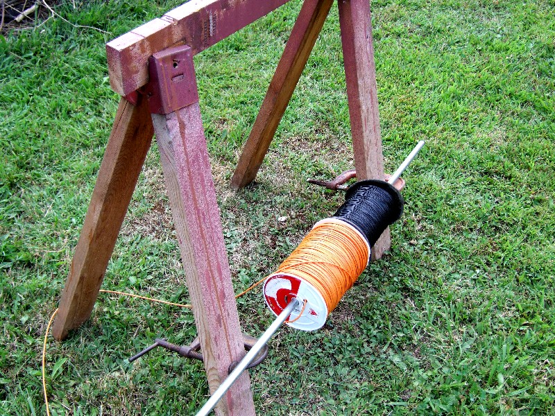 |
| Wire Dispenser |
There is no electrical value in a perfectly symmetric radial field. By perfect, I mean every wire runs in a straight line within 1 inch of the assigned angle. Still, you want to do the best you can, without losing sleep. My approach was to lay out 6 ropes in a hexagon shape that I called indicator ropes. These were marked with tape at the correct spacing for the radial location. The wires were always installed under the rope so that at the end of the process I could simply remove the stakes anchoring the rope and then remove the rope.
After attaching the ring terminal at the base, I would walk back to the wire dispenser and cut the wires. How long were the wires? The simple answer was as long as I could make them. This was in a range from a low of around 60 feet to a high of around 110 feet. Most were probably around 90 feet. After cutting the wires, I would pull them off of the ground, and make them straight going back to the base. Now this had the effect of raising the indicator rope which was over the wires. I could easily see the tape markers on the rope, even though I might have been 50 or more feet away. This made it possible to align the wires with the desired angles. I just had to position the wire under each piece of tape on the indicator rope. The ground was full of little roots and shoots, and raising the wire help find the straightest path through the obstacle course.
Here is a really poor diagram to help explain what I just said.
 |
| Radial Layout |
The antenna is in the middle. The orientation of the tower base is shown, and the antenna tilts to the top of the page. The indicator ropes form the outer perimeter of the hexagon. I used a pair of 100 foot measuring tapes to locate all of the points on the diagram. Each triangle is 60 feet on a side, with internal angles of 60 degrees. By using two tapes, and additional cross checking measurements, it's possible to create an accurately located set of points. Trigonometry really is useful! The 3 guy anchor points are the darker squares at three of the corners. The post with the W letter at the bottom is the mounting point for the winch that pulls up the tower.
The 6 radial lines are the ones that I celebrated with orange wire. I drew some tick marks on the upper left indicator rope. These are pieces of masking tape that I added to all 6 lines, going around the whole hexagon. With 120 radials, each 60 foot segment will contain 20 radial wires. Since the rope is 60 feet long per segment, the masking tape markers should be placed every 3 feet. This was easy to do by running a tape measure along each section of rope and adding a piece of masking tape where indicated.
In conclusion, I used a set of six equilateral triangles that created a hexagon to act as the grid system for the radials, and the guy anchor points. The perimeter rope had tape markers every 3 feet around its 360 foot length. When laying the radials (two are shown as dotted lines in the diagram), I aligned the wire to the markers. This procedure located the radial wire and the guy anchor points.
I anchored the ends of the radials to the ground with 6" landscaping staples. These are usually sold locally, although not in large quantities. They are used to hold down landscaping fabric and material such as pond liners. A typical price is around $2 for 12. Since I need a lot more than a few, I bought a box of 500 from a place on the Internet for $30 (baileys-online.com). Being raw steel they start to rust as soon as they come in contact with moisture, but that's not a problem in this application.
I did not try to pull each radial tight. In fact, I left a lot of slack in the line when I pushed the end staple into the ground. Because the ground is irregular, I used additional staples per radial to try and get the wire to hug the ground as much as possible. This will help in the process of having grass trap and protect the wire, and, eventually bury itself into the top layer of dirt. A tight radial wire is just an invitation to trip over it at some point. Let it lie on the ground as much as possible. I won't really know how the radials turn out until next spring, but, I bet that I could have left even more slack than I did.
The last part of the process is integrating the radial wire skirt with the ground rod. I used a pair of #12 insulated solid copper wire to connect the center of each aluminum bar to the ground rod via the bolt that holds the aluminum to the steel. That's 6 wires. In addition, I had two more pair of #12 wires that went to the brass bolts that are the mounting point for the control box. I needed to bond 10, #12 wires to the ground rod. I used a common 5/8" round screw clamp that surrounded the rod and the 10 wires. The wires went beyond the clamp for a few inches before they were all flush cut. In that last few inches, I wrapped the copper bundle with additional wire, and then soldered that whole wad of metal together. As a final step to the process, I noticed that the liquid electrical tape product was now available in spray form. I coated the clamp and the wire bundle with several layers.
 |
| Radials and the Ground Rod |
A red arrow points at a brass bolt that comes through from the inside and terminates in a wing nut. That bolt, and the bolt to the right, anchor the control box. The yellow arrow points at the coated copper wires. While I tried to coax the top of the wire, I left the bottom open. This is part of the theory - you can't keep water out, all you can do is give it a place to go.
I reused a run of LDF4-50A transmission line that I picked up from another ham. The testing and checking of that cable is described on the LDF4-50A page.
Perhaps the biggest mistake I made in my Hex Array was how I ran the transmission lines and control cables. They simply run on the ground, on top of the radial system. This ended up being a huge pain in the neck every time I want to cut the grass around the array. In order to cut the grass, I have to remove 9 UHF connectors at the center control box, and unplug a control cable. Those lines need to be rolled up to the 6 verticals and a coax switch. I then get to cut the grass, and when done, connect everything up again. Now I guess I can say that this does force me to visually check the array several times in the summer, but that's the only useful result. Everything else is a waste of time. I vowed that I would not get into that situation again.
I should also mention that I'm talking about a run of cable that is around 170 feet long, that runs from the vertical to a switching box. At that point the lines join with the lines from the Hex Array, and then head back to the radio.
What are the choices? Here's what I considered.
On ground: This is what I'm trying to get away from. The problem is rolling tractors and grass cutters over the lines, as well as sharp deer hooves. On the other hand, the cables are visible and can be quickly examined and checked. Over time, they might become partially buried, or entangled in a mess of weeds. So, even if you put them on the ground, you need a scheme that keeps them in the clear. That's an emotional roller coaster of concern about cable damage if you are using a grass cutter or line trimmer. Perhaps another idea would be to periodically spray the lines with something like RoundUp to keep the plants away. The lines will come in contact with water, and a low spot might even lie in a shallow pool. Perhaps the safest approach would be to use direct burial cable, but place it on the ground.
Elevated: Figure out a strategy that elevates the cables a few feet in the air. What I really like about this idea is that the wires will spend the minimum amount of time in contact with water. Sure, rain and snow will fall on the lines, but it will all drip off and completely evaporate. Every other choice, even buried in pipes, probably places the cables in substantially more water contact. An elevated line system could be easily maintained and extended, and splices and connectors should not be a problem. Elevated lines suffer from creating a barrier in an otherwise open area, and, the lines run a higher risk of picking up antenna currents. Cutting around the elevated lines can be a problem, depending upon the height and environment.
Direct Burial: Bury the lines a few inches below the surface. I've done this here for other antennas, and it's worked out OK. Using cable rated for direct burial is the safest move, although it costs more. The line is certainly protected, and mowing around the lines is no problem at all. On the other hand, it's impossible to inspect. Finding a break or fault in the line could be very messy and time consuming. Adding additional lines is very hard. In fact, the existing lines become a mine field, since you don't want to hurt those while adding more. I would be very concerned about burying splices/connectors, unless I really had confidence in the splicing technology. The lines might be in a wet environment most of the year. Some folks have mentioned problems with animals digging and gnawing. I've fortunately never had that problem here. If so, direct burial would stop making any sense. If you do anything with burial, and also have radial wires on ground, you've got to think about how the lines run. I would hate to bury a transmission line and control cable under a radial system, and then discover there was a problem. I think that the only sane solution would be to run the lines radially, just like the radials, so that no radials cross over the lines.
Run in underground pipe: This always seemed like the Cadillac way to go. Bury some plastic pipe underground, and then run the lines in it. Run additional pull lines so that you can add new cables. This is probably the most expensive approach. The lines are out of sight, so grass cutting is not a problem. Even if you plunge a sharp shovel into the ground and hit the pipe, odds are that you will not do any damage. I guess that my problem is water. Over the years, if I've learned anything, it is the following:
You can't keep water out, all you can do is give it a place to go.
So, I've always viewed the end point of this approach as lines running in a pipe filled with water - no matter what you do to try to avoid it. Since pipe large enough to have room for expansion is going to be a few inches in diameter, the burial process probably means using a trenching machine (DitchWitch) as opposed to a slit with a sharp spade. More work and cost. I've wondered if the water problems could be dealt with by adding holes to the pipe and burying it in some gravel, sort of like a septic system. Even if it works, it's a lot of work and expense. At least in a pipe, the lines are protected from animals.
On ground protected: This is the method I ended up using. The idea was to lay the lines on the ground, but then cover them with a material that would protect them. The material would have to be tough enough to allow the tractor and grass cutter to drive over without damage. The cover also needs to be easy to remove so that the lines can be maintained and expanded. Speaking for myself, the material should also be inexpensive and not fancy or exotic, since it might be damaged, and need repair from time to time.
After looking at a few ideas, the solution I used was to take 2" plastic electric conduit pipe and rip it down the center, creating two half pipes that would be put over the cable. Now one idea might be - gee, just lay a complete pipe on the ground. Well, that's twice as expensive, and given my feelings about water, it would end up trapping water. It also would stand taller above the ground, making a bigger obstacle for the tractor and mower. The tractor might tend to push the pipe as opposed to roll over it. Finally, the cable would be threaded through an unbroken pipe. So, it would be hard to get to a particular section.
What's nice about electrical conduit is that it is cheap - around $3.50 for a 10 foot length at my local Home Depot. One 10 foot length will provide 20 feet of cover, since I'm ripping down the pipe. One of the ends has a bell flare so that no additional couplers are needed. This would not be the case with normal PVC pipe. The color is gray, so it tends to blend in better than stark white. It claims to have some UV protection. I thought about actually gluing several sections together to make a sub assembly, but, in the end, it was better to use no glue at all, and use long spikes to pin the pipe to the ground at every 10 foot junction. This means that every 10 foot section can be easily removed and replaced.
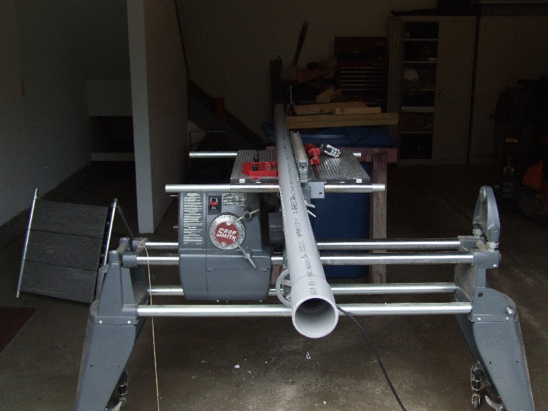
For the prototype, I ripped a pipe on a table saw. This worked, but created a mountain of cuttings. In the end, a band saw was used for the rest of the pipes since it has the smallest kerf. Here is a picture of that first experimental cut. It's good to do this outside if you can, it makes a nasty mess.
 |
| Ripping Electrical Conduit |
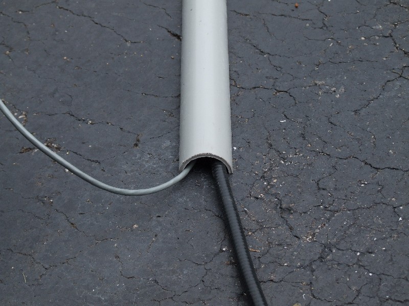
Once I had a half pipe, I put it over a sample of the transmission line and control cable to see how much clearance I had.
 |
| Test Fit |
There was room for the two cables, and even room for expansion. The bump on the ground was only around an inch, so the profile is low too.
Once I had the cables on the ground, I started to put 10 foot sections of the conduit over the cables. I used one foot long landscaping spikes to pin the conduit to the ground. Here is a look at a spike, without the next section in place. Obviously you need to make sure you don't drive the spike into the cable! That would be bad.
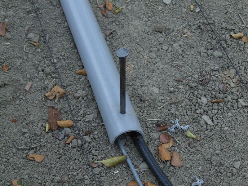 |
| Conduit Spike |
The black lines to each side of the pipe are ground radial wires. The cables run in a straight line away from the antenna, just like a radial line. This means that I am between two radials, and nothing needs cross over another type of line.
Here is a look at an overlapped seam, using the flare provided in the pipe. It's been a few weeks since this was installed, so the raw steel is already showing some rust. Using a small pry bar or claw hammer, the spike can be removed.
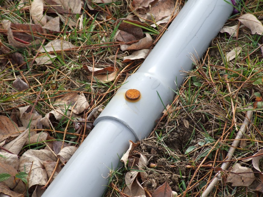 |
| Conduit Junction |
Finally, here is a look down all 170 feet of pipe, from the coax switch towards the antenna.
 |
| Conduit Run |
The pipe is straight so that it runs directly along the radial path. What looks like a trench to the left of the pipe is where the lines to the previous 160 meter vertical ran. That has all been removed.
So far, this is working out well. I can drive the tractor over the line without fear of damage. Grass cutting is not too bad either, although I won't really know about that until next year when the grass fills in around the entire length of the pipe. If I need to get at the cables, I can pull two spikes, and expose a 10 foot section.
One last suggestion. Although it probably looks like I have nice flat ground, it isn't. There are ups and downs and ruts and other deviations from flatness. When I first put the conduit over the cables, and only spiked them every 10 feet, the cables would try to scoot out from under the pipe in a few places. A large part of that was due to the transmission line, that had been coiled up for years, and is pretty stiff. My solution was to put a cable tie around the pipe every few feet. I had to make sure that the cables were up inside the pipe before adding the cable tie. This guarantees that the cables are tucked up inside the pipe, and it's all one assembly. That really adds to the protection provided by the pipe, since the contents cannot sneak out. The pipe does not just run over the cable, it actively holds the cable within the half pipe.
The antenna is guyed in three directions, with 120 degree spacing going from point to point. As I've discussed before, I like to be able to cut the grass and perform normal yard work around my antennas. This includes using tools like line trimmers that can be powerful and dangerous. I also have a leash of deer that are always drifting through the yard, and they are capable of most anything. Check out what they did once in the past. Guy line anchor points are places where lines come down to the ground, where they are vulnerable to abuse and damage and even vandalism. Even if you don't damage them, the angle of the line tends to create zones under the lines where you can't easily cut because the line is too close to the ground as it rises in the air towards the antenna in the center.
To try and minimize that problem, I decided to create what I would call elevated guy anchor points. I took 8 foot long pressure treated 6" X 8" timbers, and sunk then 3 feet into the ground, leaving around 5 feet above ground. Near the top I drilled a hole through the post and attached a large screw eye bolt. The guy lines, 3 per anchor point in the first version, attach to the screw eyes with brass clips. For a final bit of safety, I threaded a small diameter steel cable through the eye bolt and then the closed rings of the clips. The ends are then brought together with a wire rope clamp. While it's still possible to cut a line, or even unscrew the clamp, all I'm trying to stop is what I would call the lazy casual vandal, who could quickly remove a clip and then walk away. Maximum damage, minimum investment. Now, they would have to spend some time and potentially have a knife or wrench with them. (I should mention that I live in a rather rural area, and in the 23+ years I've lived here, I've never seen one unknown person walk on the property)
With the attachment point around 5 feet in the air, it's easy to walk and work around the posts. I can use a line trimmer right up against the bottom without getting anywhere near the lines themselves. And, I hope that deer will not be able to get in trouble if they stop to visit. I stained the posts brown with a typical deck stain product, and they nicely blend in with the surroundings.
Here's a case where I would have to rethink and reanalyze this approach if the tower could be climbed by humans. Using wood as part of a guying system should only be done if carefully and correctly engineered. In my case, I don't care, since the towers will never be climbed. Practically speaking, the posts are very strong, and I suspect they would stand an amazing amount of load before breaking. Certainly in my installation the UV Dacron rope used for the guy lines is by far the weaker link.
Although I dug the base holes by hand, I used a rented powered post hole digger to dig these three holes. It cost around $40 for a 4 hour rental, but the holes were drilled in a matter of minutes. If you need to dig several round holes, this is the only way to go.
Here is a freshly drilled hole with the post ready to be dropped in:
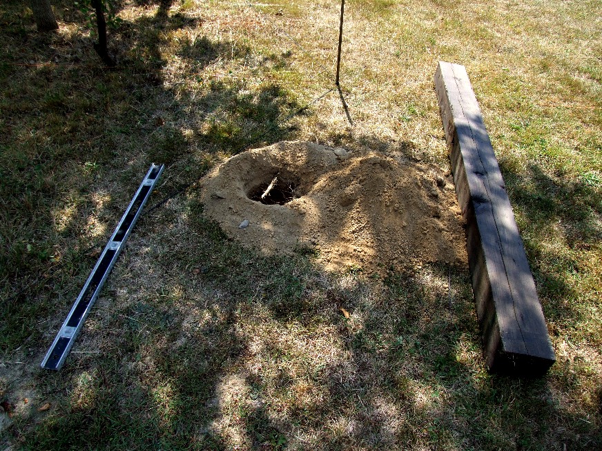 |
| Hole and Post |
Here is a close up of the safety cable threading through the various closed rings. The cable is plastic coated steel rope.
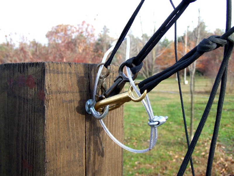 |
| Safety Cable |
Finally, a fully operational post.
 |
| Post in Profile |
Excess line is hung from a hook screwed into the post under the eye. You might ask - Hey, Greg, why not just cut off that excess rope? It's a good question. The problem is that I need extra length so that I can walk the guy lines around the small trees that live between the guy posts and the center antenna. If the area was completely cleared, then it would be possible to cut the lines to length after the first installation, and even leave them clipped to the post as the antenna tilted up and down. The little trees keep me from being able to do that. So, my brass clips are not at the end of a line, but in the middle.
That gets into the whole topic of knot tying. I'm very lucky in that my friend and business partner who helps me out with all of these projects is also a sailor, and knows all about knots. Without his knot tying knowledge I would be sunk.
The three posts are located 60 feet from the base of the antenna. They are indicated on the diagram in the ground radial section. The lower two sets of guys are 5/16" UV/Dacron rope. The top set is 3/32" UV Dacron rope.
One last point. One of the three posts is special in that I mounted a winch near the bottom of the post. This is the winch that pulls up the tower to vertical from horizontal. I put the winch at the bottom of the post to reduce the horizontal bending stress on the post, and, to keep the winch cable well under the guy lines that are up on the top of the post. The winch is rated for well over 1000 pounds. The winch uses steel wire rope around the drum, but it does transition to synthetic rope before reaching the raising fixture pulley. This winch is called a brake winch, meaning that it does not use a ratcheting mechanism. At any point in bringing in or letting out line, you can release the handle and it will stay at that point. I have this sort of winch on my crank up tower, and it's worked well for over a dozen years. Here is a picture of the winch.
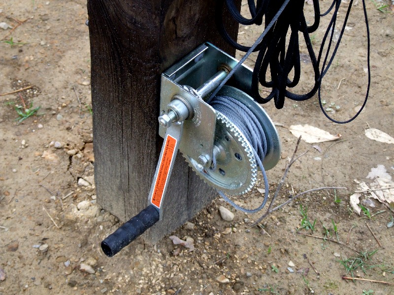 |
| Tower Winch |
The winch can be removed without too much effort, and the plan is to bring it inside and out of the weather, especially over winter.
With two towers, 9 guy lines, 4 raising fixture guy lines, and two pull lines, this 160 meter vertical ends up more like a sailboat. Making this all work came down to the lines and rigging. There is a lot of it, especially when actively raising or lowering the antenna.
In the first section of this page I dubbed this antenna the Wet Noodle 90 because of the flexible 40 feet of tubing on top of 50 feet of tower. Don't believe me? Here is a picture of the antenna tipped over and supported at two points.
 |
| Wet Noodle 90 |
Hopefully this makes it obvious that the second support rope is needed. I added a red arrow to point at the guy ring that serves as the second support point, at the 70 foot level.
The tower is pulled up with a 1/2" synthetic rope that runs over a pulley at the top of the raising fixture. That pulley looks like:
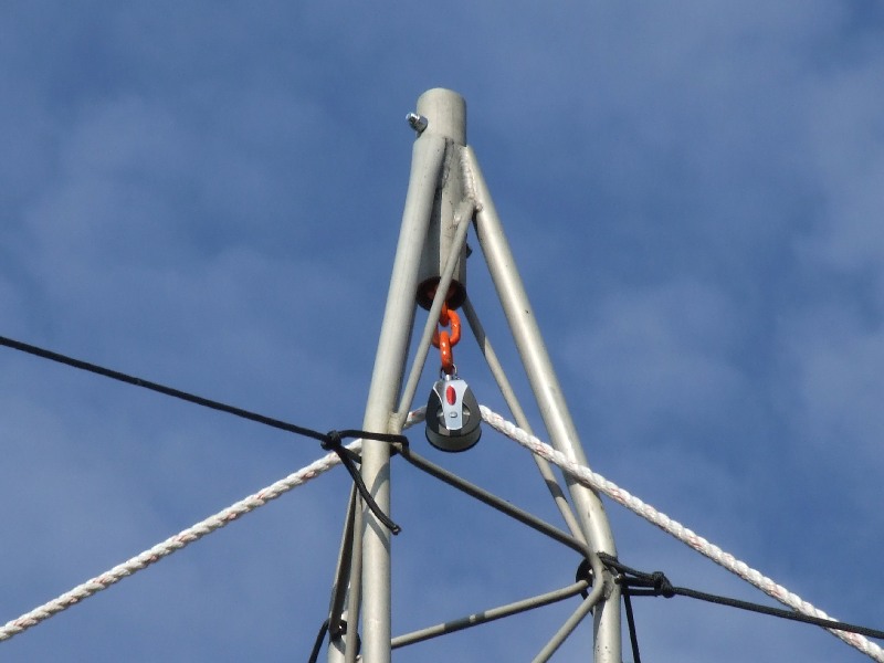 |
| Main Pulley |
One end of this rope attaches to the antenna tower with a bridle. The other end has an eye splice and thimble. The steel rope on the winch attaches to the thimble. The pulley in the picture is suspended by a short length of chain with a cute orange plastic coating. The top of the chain is suspended by the bolts that go through the tube at the top of the raising fixture. This turned out to be a very useful solution because the pulley can rotate and swing while inside the top of the tower. This allows the main rope to enter and leave without being forced into some rubbing or friction alignment.
The other reason that it was good to mount the main pulley a little under the top of the raising fixture is so that the second pulley for the second rope could be placed at the top of the tower. It looks like this:
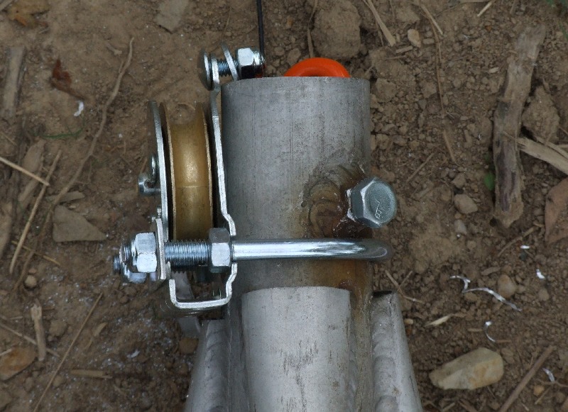 |
| Secondary Pulley |
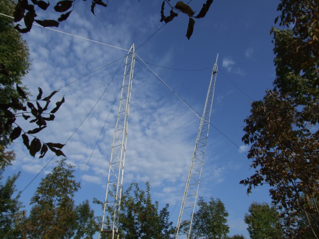
Here is a picture of the two towers during some early testing. I don't have any pictures of the two line system because I had to operate a line, and not the camera.
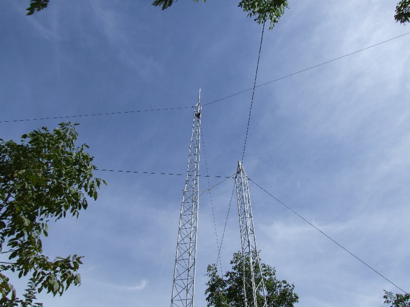 |
| Two Towers |
Although the wet noodle tubing is not installed in this picture, you get the idea of how this all looks as the tower tilts down.
 |
| Antenna Tower Tilting Down |
So what's the hard part of raising or lowing the tower? So far, the answer is starting to lower it. It just wants to stay vertical. I have to push on the tower to keep tension on the pull rope until the weight of the tower starts to pull horizontally. I need to figure out a better system to encourage the tower to tilt over as the winch releases the tower.
Back to the 2010 W8WWV Vertical Page
Back to my Experimentation Page