 |
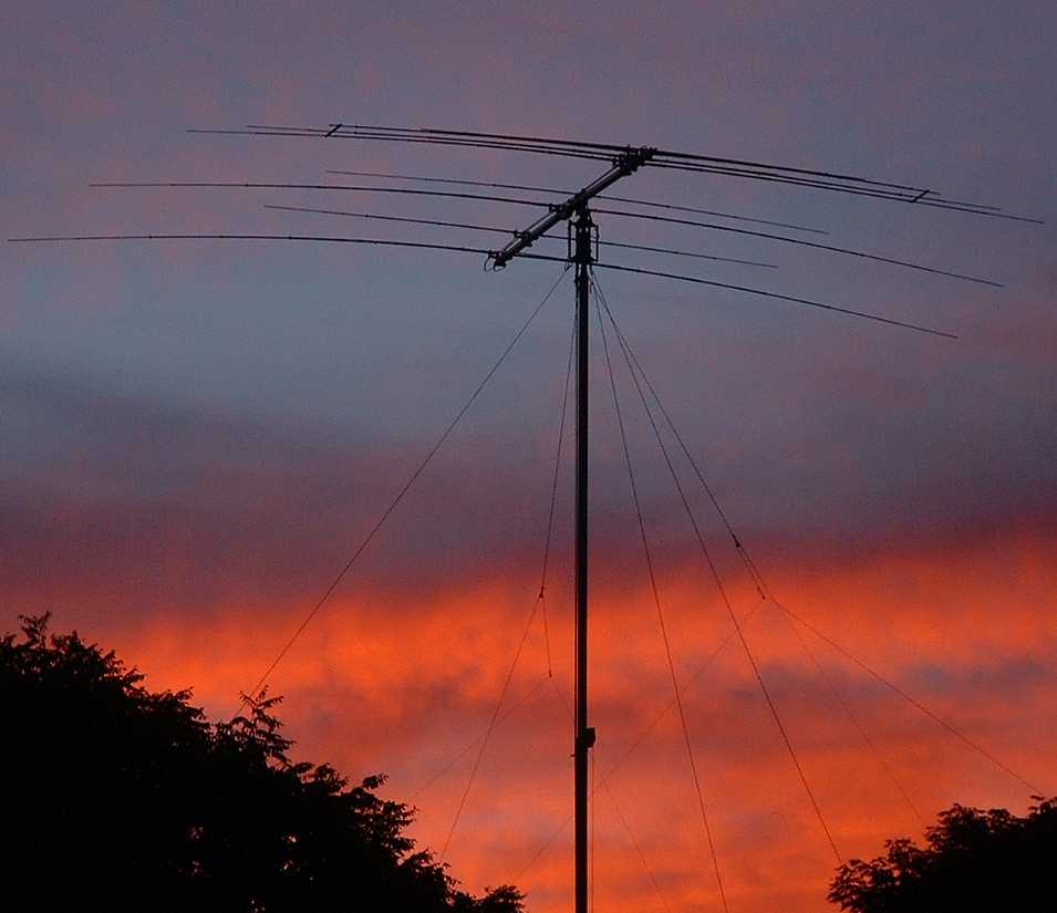
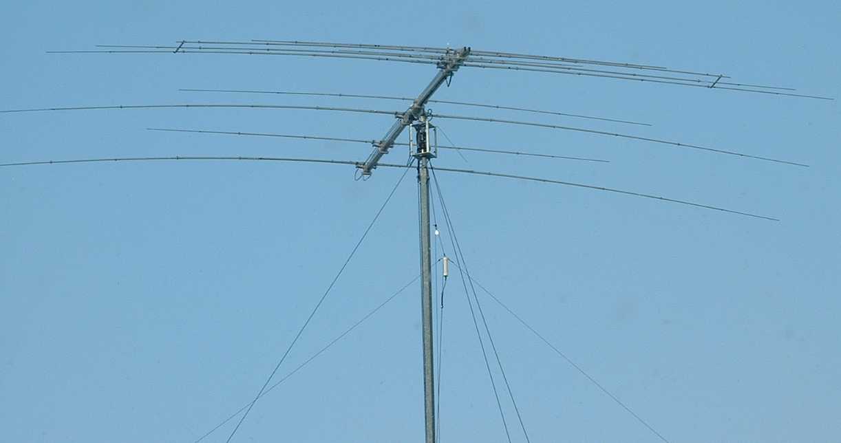
| Sommer XP506 at Sunset (Click for a larger view) |
Greg Ordy
|
|
| Sommer XP506 at Sunset (Click for a larger view) |
I really like my Sommer XP-50 antenna. My antenna covers 20, 17, 15, 12, 10, and 6 meters. I have never tried the 30 meter kit. I initially installed the 40 meter kit, but I found that any other 40 meter antenna I had exhibited higher performance. On 40 meters, the antenna operates more as a mass of resonant metal as opposed to a directional antenna. Still, if you don't have room for other antennas, you can get on 40 meters with this single antenna.
The antenna has three full-size 20 meter elements that are all driven by a set of phasing lines. The basic design is extensible, and you can configure the antenna with either 2, 3, 4, or 5, 20 meter elements. Shorter elements are placed between the 20 meter elements, and they operate on the 12 and 10 meter bands. The front of the antenna includes several driven and parasitic elements that are tuned to 17, 15, 10, or 6 meters. The Sommer web pages describe how the various elements are used on the different bands. In general, most all elements are used on all bands, providing higher performance, and fewer wasted elements, which are not used (electrically invisible) on certain bands.
The Sommer numbering scheme suggests that the number of functional bands should be added as a final model number. Although my basic antenna is designed for 4 bands (20, 15, 12 and 10 meters), with the 17 meter and 6 meter optional kits I really have an XP-506. With 30 and 40 meters you would have an XP-508. 8 bands from a single product is a great deal of frequency coverage for an antenna.
One feature of the antenna is that it does not have loaded or trapped elements. This means that there is no opportunity for loss due to those devices. The only question is whether or not the antenna provides gain on each band. With some antennas, bands such as the WARC bands were added as an afterthought, and while they are resonant on those bands, the performance is not very good. In order to have more gain in some direction, you must have less gain in other directions. Antenna patterns are often compared to inflated balloons. If you squeeze them, you get a bulge (gain) in some direction, but only because some other direction is constricted (less gain). So, if we can measure the antenna pattern, we can get a sense of the antenna gain potential.
The most common method used to examine a rotatable antenna pattern is by watching the S meter as the antenna turns. This is a rather imprecise technique. I have been working with my S Meter Lite software to generate more accurate antenna pattern plots. I thought that testing my XP-506 would be a good vehicle for evaluating the software as well as the antenna. This web page presents some background on the antenna construction and installation, but is mainly designed to explore antenna pattern plots for each band. My thesis is that the presence of an asymmetric pattern will be the indirect signature of gain, which is what I am looking for on each band. Since there are no lossy devices to overcome, any gain is a net positive effect on performance.
Over the last several years I have used this antenna mounted at approximately 60 feet off of the ground. I have driven it with 1500 watts. That set up has always worked well, and I seem to break DX pile-ups very quickly - on all bands. If anything, I wish that I had the tower capacity for a larger Sommer beam.
I ordered the antenna by telephone, directly from the factory. I was quoted an 8 week delivery time. I was pleasantly surprised when they called me after 6 weeks to tell me that my antenna had shipped. They did not charge my credit card until they shipped my antenna. The antenna arrived in several small but long boxes. It could be shipped by UPS. I had several conversations with the factory during the construction of the antenna. In all cases they were a pleasure to deal with, and provided prompt and detailed information.
The antenna was constructed over two days. It was not difficult to assemble as a one-person job, with no more than common hand tools. The most important tools are nut drivers, needed to tighten the many hose clamps used to establish the elements, which are made of telescoping aluminum tubing.
The antenna has several interesting construction details.
The boom is realized from a pair of parallel rectangular aluminum extrusions. These tubes are accurately and constantly spaced by notches in the perpendicular element mounts, which are cast aluminum. The elements taper down to 1/4 inch, which means that they will sway in the wind. The antenna is very sturdy, and has easily survived many harsh Ohio winters. This has included some serious ice loading. The antenna has a balun which is rated at 2 KW. All materials are mainly aluminum or stainless steel. There are a few plastic centering inserts used as insulating spacers between the elements and the element mounts. These do not appear to have deteriorated due to cold, heat, or sun exposure (see the maintenance section further down this page).
The antenna has a reasonable wind load for a 16 foot boom. It weighs approximately 70 pounds, which is on the heavy side for that length. I attribute that to the rugged construction.
Here are some pictures taken during the construction process. Please click on a picture for a larger view.
 |
 |
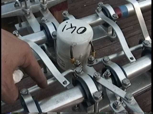 |
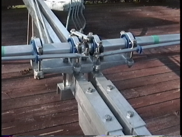
| Double Rectangular Boom | Element Mount | Driven Elements |
The element centers come with a colored tape code that makes it easy to get the right one in the right place. The middle picture shows the cast aluminum element mount, and the blue plastic insulators.
The only tricky part of construction was bending and adjusting the aluminum bar stock used to connect all of the front driven elements to the balun. I had to bend them in order to get them to bridge the several connection points. Depending upon the optional kits installed, the number of connections at the front of the antenna will change. I suspect that the same set of parts are used no matter what configuration is present. This leads to some customization for each antenna. In the right picture, the two aluminum straps have to be bent to attach to the pair of bolts that combine the elements and the balun output.
As mentioned earlier, all of the 20 meter elements are driven. A pair of parallel phasing lines run down the length of the boom. When the lines get to a 20 meter element, they attach to the element, and cross each other (180 degree swap). The middle picture shows a clear plastic spacer which helps fix the position of the lines when then run over an element which is not a 20 meter element. The phasing line reversal can be seen in the lower right corner of the right picture.
I installed the antenna on top of a US Tower MA-550, which is a 55 foot crank-up tower. I have the tilt-over base which adds approximately 2 feet under the lowest tower section. The rotator is a Yaesu G-800SDX, which is enclosed in a metal cage which I call the rotator cage. This cage is designed to provide mechanical isolation for the rotator on top of the tower. Since the tower is tubular, it terminates in a round plate welded to the end of the top section. There is no opportunity to locate the rotator inside of a typical triangular tower section, which provides significant protection. With the length of the rotator cage and the short mast that extends above the cage, the antenna ends up at approximately the 60 foot level.
The 60 foot level hopefully provides for a primary lobe with a low take-off angle across the various bands. Heights which are lower or higher can be useful for specific bands, but only at the expense of performance on other bands. Most of the common antenna books discuss the various issues that are a function of antenna height. An excellent reference is Yagi Antenna Design, by Dr. James Lawson, W2PV (SK). In Chapter 5, the Best Height section suggests that in order to cover the important range of elevation angles from 3 to 17 degrees, the antenna should be approximately 1.5 wavelengths above the ground. The 60 foot level is approximately 1 wavelength on 20 meters, and 2 wavelengths on 10 meters, straddling the suggested height.
With a crank-up and tilt-over tower, I can adjust the antenna at the ground level. This has proven to be quite convenient. Cranking both winches does take a little time and muscle, but it's more than worth it for the ease of adjustment and maintenance. The shipped element dimensions apparently are designed for typical European installations where the antenna is relatively close to the roof. Since mine was much higher off of the ground, my final dimensions were slightly altered from the dimensions in the documentation. The folks at the factory were very helpful in discussing these changes.
 |
 |
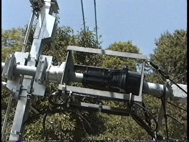
| XP-506 and Rotator Cage | Ground Level Adjustments |
In the left picture you can see the antenna on the left, then a Yaesu thrust bearing (GS-065) mounted on top of the rotator cage. The short mast terminates in the Yaesu rotator.
When I need to adjust the XP-506 I can make all adjustments at ground level, after the tower is lowered then tilted. The thin element on the bottom side of the boom is the 6 meter forward element.
The antenna pattern plots were made with the S Meter Lite program. It took some time to develop a testing strategy that produced what I considered to be valid results. This strategy is described on another page. The 40 meter coil was not on the antenna when these measurements were made.
The pattern of an antenna will be a function of the height of the antenna, as well as the design of the antenna. My plots reflect a single take-off angle, which is rather low. Ideally, a range of elevation angles should be measured, perhaps from 5 degrees through 45 degrees. This range represents most typical take-off angles. In these plots, I consider the RDF to be the significant data, as well as the overall shape of the plot and the 3 dB beamwidth of the antenna. Since the plot is being conducted at a single take-off angle, the RDF does not refer to the entire pattern, but just the pattern at the single measured take-off angle. The RDF is the maximum signal strength minus the average signal strength captured over 360 degrees of antenna rotation. This is a self-relative measurement. There is no measurement of absolute gain. Gain is inferred from the existence of a focused pattern and the absence of lossy elements such as loading coils or traps.
In order to have some sort of comparison reference, I looked at two EZNEC antenna models. A simple dipole model, and a high-performance 5-element Yagi. I ran the models on 20 meters, each at a height of 60 feet, which is almost one wavelength above ground. As the frequency goes up, the constant 60 foot height of the real antenna will represent an increasing electrical height. That will tend to lower the primary lobe.
Here are the dipole azimuth and elevation plots, followed by the Yagi plots.
 |
 |
| 20 Meter Dipole Azimuth Plot (@ 60') | 20 Meter Dipole Elevation Plot (@ 60') |
 |
 |
| 20 Meter 5-Element Yagi Azimuth Plot (@ 60') | 20 Meter 5-Element Yagi Elevation Plot (@ 60') |
The RDF of the dipole is 8.22 dB. The Yagi RDF is 15 dB. Those RDF values were computed across the entire sky, not just a single take-off angle, as will be the case in my measurements. The take-off angles for the azimuth plots is 15 degrees. The 3 dB beamwidth is 80 degrees for the dipole, narrowing to 55 degrees for the Yagi.
I don't expect to be doing any direct comparison between these plots and my measurements. They serve to provide some small suggestion of what a lowly dipole, and an excellent Yagi look like under similar circumstances. The pattern of an antenna, especially the nulls, is typically highly frequency dependent. The frequency of maximum gain, maximum F/B (front to back ratio), and minimum SWR are usually never the same.
It's also true that as the frequency goes up, my 60 foot high antenna will be at increasing wavelengths above the ground. That will influence the pattern to a different degree for each band. The main lobe will tend to tip down.
I also found it helpful to refresh my overall thinking about and expectations of the typical Yagi. A good on-line resource is a series of pages created by L.B. Cebik, W4RNL. On these pages he looks at the characteristics of a three element Yagi. As expected, gain tends to change very little over the band, but front to back performance can vary by as much as 20 dB or more. As said before, nulls in resonant directional antenna patterns tend to be frequency dependent. For that reason, I will make several antenna pattern plots in each band. My target frequencies are:
| Antenna Pattern Plot Target Frequencies | |||
| Band | Low (MHz) | Mid (MHz) | High (MHz) |
| 20 Meters | 14.000 | 14.150 | 14.300 |
| 17 Meters | 18.068 | 18.120 | 18.168 |
| 15 Meters | 21.000 | 21.150 | 21.300 |
| 12 Meters | 24.890 | 24.940 | 24.990 |
| 10 Meters | 28.000 | 28.250 | 28.500 |
| 6 Meters | 50.000 | 50.100 | 50.200 |
There is nothing special about these frequencies, they are designed to represent either the entire band, or the part which is of most interest to me. The tops of 10 and 6 meters are the only real holes.
The most accurate pattern plots would require that my S meter be calibrated for each band. Since that's a lot of work, I used the default 20 meter calibration data, which I suspect is accurate enough for the purpose of determining if the pattern has well-defined lobes and nulls.
By the way, if you have an EZNEC model of the Sommer beam, I would like to request a copy.
The SWR graphs were made with my AEA CIA-HF antenna analyzer, and a custom program which produced the graph from data downloaded over an RS-232 connection. The CIA-HF was adjusted to capture the entire amateur band (US allocation) with the minimum amount of out-of-band frequencies on each side. The analyzer requires the specification of a center frequency and a sample width. The sample width is selected from a built-in set of choices. A single scan samples the antenna at 100 frequency points. The points are equally divided below and above the center frequency, spaced by the sample width. Each graph contains SWR data captured at 100 points across the frequency range of the graph. The points are connected with straight lines. So long as the samples do not get too far apart in frequency, the curve will appear quite smooth.
Dotted vertical lines indicate the center frequency of each graph, as well as any amateur band edges (US allocation). The SWR 2.0 horizontal line is also shown.
SWR is not a measure of antenna performance. As has been said many times, a dummy load has an excellent SWR, but is hardly a good radiator. On the other hand, most transmitters and amplifiers will only produce their maximum rated output power if the SWR is lower than some threshold value. The limit is often times 3.0. If the SWR is higher than the limit, the transmitter may produce less output power, or it might shut down completely. SWR, therefore, becomes a factor that enables the use of a frequency (for transmission), but says nothing about the antenna performance at that frequency. It is also true that transmission line loss increases when a line is not terminated in its characteristic impedance. For open-wire line the additional loss is small, but we are talking about coaxial lines in this case.
The SWR measurements were made at the end of approximately 65 feet of LMR-400UF transmission line. The cable had been purchased and installed a few days before the measurements were made. The antenna was approximately 60 feet off of the ground. No other antennas or wires were within at least 100 feet of the tower. On the day of the measurements I had adjusted the XP-506 for the lowest SWR values at my target frequencies. Adjustments were made according to the tuning information provided in the written instruction manual.
The radios used for the pattern measurements were described earlier in this section. An additional 200 feet (approximately) of transmission line (9914F) was inserted in the path from the base of the tower back to the station radio. I made the SWR measurements at the base of the tower in order to have the shortest possible transmission line length. For pattern measurements, however, I simply had to get back to the radio, and any additional line loss will not change the pattern, since it is a relative measurement.
Please click on a graph for a larger view, which will be necessary to read all of the text.
 |
| 20 Meter SWR versus Frequency |
The 20 meter SWR is very flat. This is the signature of driving all of the 20 meter elements through phasing lines. This technique has been used on other antennas, where more than one driven element is combined with additional parasitic elements. KLM and other manufacturers have used this approach.
 |
| 17 Meter SWR versus Frequency |
17 meters is the one band where I might lower the resonant frequency approximately 50 KHz. This would put the SWR dip right in the middle of the band. The 17 meter SWR dip is very narrow, and the band is also narrow. Please see the overall HF SWR sweep later on this page. Using the Sommer documentation as a guide, I would need to lengthen the 17 meter element by approximately 3/16".
 |
| 15 Meter SWR versus Frequency |
 |
| 12 Meter SWR versus Frequency |
 |
| 10 Meter SWR versus Frequency |
 |
| 6 Meter SWR versus Frequency |
In order to get an overall look at the SWR of the antenna across the entire upper HF bands, I performed a custom sweep from 13.5 MHz through 29.7 MHz. This broad sweep should reveal all of the SWR dips previously graphed, as well as any that might exist between the amateur bands.
 |
| SWR versus Frequency (13.5 MHz through 29.7 MHz) |
This SWR maximum on this graph is set at 5.0, so some of the high peaks are truncated. All of the SWR dips correspond to the amateur bands.
This antenna has exceeded all of my expectations. The data I collected suggests to me that the antenna has significant gain on all 6 bands. My only evidence to back up that statement is that the antenna pattern is focused, with typical lobes and nulls, and there are no lossy elements to absorb power.
The 2.0 SWR bandwidth does not cover all bands, but more than covers the parts that I am interested in. For example, I do not operate both 10 meter CW and 10 meter FM (both ends of the band). The band adjustments do interact. I can believe that there are sets of element lengths that have increased SWR bandwidth, and even increased performance. In the absence of an antenna test range, and a lot of free time to experiment, those combinations are hard to find. If you raised or lowered the antenna, those points would shift.
It is probably also true that there are element length combinations which would shift the deepest pattern nulls. Trying to play that game can become very complex, given the interaction between elements on different bands. And, even if you could shift the deepest nulls to the most desirable part of each band, the SWR would probably shift substantially. This would be adjusting the antenna to improve the RDF (receiving directivity factor). If this were a 40 or 80 meter antenna, it would be worth it to move the maximum RDF to a specific target frequency. This would optimize the signal to noise ratio. Since the upper bands tend to have much less noise, it is less important. While nulls tend to come and go quickly as a function of frequency, gain typically moves much more slowly.
Some of the front elements are parasitically coupled to the other driven elements. Some elements are directly fed, and others are parasitic. I assume that the choices made provide the best performance. This so-called coupled-resonator principle has been described in many publications. It's interesting to note that the higher frequency coupled elements often have a smaller bandwidth than the lower frequency driven elements. Please consult ARRL Antenna Compendium, Volume 5, page 109 for more information. This article, The Coupled-Resonator Principle: A Flexible Method for Multiband Antennas, by Gary Breed, K9AY, discusses the history of this technique, as well as some formulas for building your own. The Sommer design takes this idea, along with the driven 20 meter elements and the additional 10/12 parasitic elements to create an overall design which is quite unusual. The patterns are not the same as the typical Yagi, with half-wavelength elements. One would not expect them to be, and it makes little difference, so long as a focused pattern can be generated.
While it's very hard to argue with stacked monobanders on separate towers, I'm more than happy to use my XP-506 on a 60 feet tower. If I had the room for expansion, I would like to try a pair of stacked XP-806's on a 120 foot tower. For my operating needs, this would represent the ultimate antenna for 20 through 6 meters.
Here is picture of the Sommer XP-506. Please click on the picture for a large and detailed view. An 80 Meter Inverted Vee is located under the beam. This picture also shows my rotator cage on top of my tubular tower. Three lightly-loaded Dacron lines provide anti-sway support.
 |
| Sommer XP-506 with 80 Meter Inverted Vee |
In October of 2002 it was time to change the wire antennas hanging off of my tower which is topped by the XP-506. With winter approaching, this also seemed like a good time to perform maintenance on the beam. One of the tasks which I really wanted to do was to replace the transmission line going up to the antenna. I had recently learned that I had used some transmission line that did not have a constant impedance. While I believe that its loss was low, the line was useless if you wanted to make accurate measurements through it.
I lowered the tower, then tilted it over. I removed the wire antenna support ropes and replaced the transmission line with LMR-400UF. I raised the antenna and decided to check the SWR on all of the bands right at the base of the tower. As I checked the bands, I was dismayed to find two conditions. First, the lowest SWR points were not where I wanted them. I somewhat expected that, since I had readjusted the Sommer antenna after I put up a pair of 40 meter delta loops on the tower under the beam. With the loops gone, some shift was expected.
The more serious problem was that the SWR tended to jump erratically. The jumps would begin as I started to rotate the antenna, suggesting it was a mechanical problem - but where?
I decided to go over the entire antenna and check every connection and clamp. While I have brought the front of the antenna to the ground many times over the years, I don't believe that I ever examined the rear of the antenna - after it was installed. I rotated the antenna so that the rear was pointing in the direction of my tilt-over tower, and brought the rear to the ground.
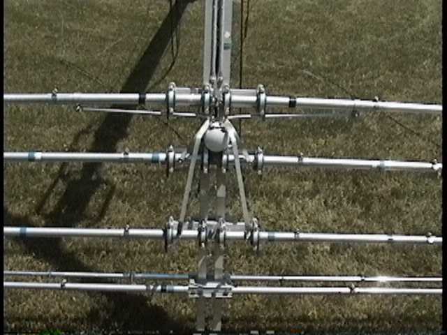
Armed with all of the necessary nut drivers and sockets, I started to check every connection. That must have been my lucky day, since within a few minutes I discovered a broken support for the phasing line right at the rear element. At this point, I was not sure if this could be my problem, but it certainly wasn't a correct situation. Here is a picture of the broken part.
 |
| Broken Phasing Line Spacer |
As I looked at the blue plastic support ring, I was thinking about how many days it would take to obtain a replacement from Sommer. In one of those out of the box thinking moments, I noticed that the 10/12 meter element right in front of the last 20 meter element had the required part, which was not being used since that element is not driven (no phasing lines). So, it seemed as if I could swap the two pieces, placing the one with the broken support tab on an element where it wasn't used, and install the unbroken part on the 20 meter element.
The swap was successful, although it took about 30 minutes. Much of the hardware on each element mount had to be removed or loosened to free the blue spacers. By the way, I discovered that the clamp attaching that phasing line to the element was loose. This was the only other loose connection that I discovered. I wonder if the additional movement of the phasing line, even if only a very small amount, caused the bolt at the end of the line to work loose?
When I cranked the tower up, I was very happy to find that the SWR was now stable, even as I rotated the antenna, or as the wind blew.
I don't believe that the phasing line ever shorted out. It simply could move (waggle) a relatively small amount near its intended position. This was enough movement to cause the SWR to jump.
The moral of this story is to make sure that the phasing lines are held firmly in place. Even a little bit of movement will cause problems.
In October of 2006, I had the tower lowered to change the pulley that is used with my 80 meter inverted vee. I happened to notice that the phasing line support tabs were broken off of both sides of the rear element. Although this included the support tab swapped in 2002, I had not noticed any instability in the SWR readings. Rather than swap support rings within the antenna, I decided to order some new support rings. The factory quickly sent my out 5 replacement rings, which cost $7 (USD) each (October 2006). The rings are made of Lexan (polycarbonate), and should have a high degree of UV damage resistance. Still, my antenna has spent nearly 10 years in the sun, with hot summers and freezing winters with lots of snow. I figured it was time to use some new spacers, and not just swap within the antenna. Other than the balun, these spacers are the only non-metallic parts of the antenna. While they are quite durable, at my site at least, they don't seem to last forever. Since all of the problems have been at the rear element, perhaps the loads on the tabs are greater in that position?
As I examined the antenna more closely, what had happened, to one half of the element, was that the element was slowly working its way out of the center-most support tube. The hose clamp was tight on the overlapping telescoping tube connection, but the element still moved outwards by approximately 2 inches. This movement strained the phasing line tube, and the support tab. I suspect that some sort of mechanical resonance effect was taking place. The one side of the 20 meter rear element just wanted to move outward, even though tightly clamped. After putting it all back together, I added a second clamp.
Back to my Experimentation Page