 |
| IC-706 Accessories |
Greg Ordy
When I first received my 706MKIIG, I mounted it in my minivan, and starting working mobile with a set of hamstick-style antennas. After several months of mobile operation, I had several situations where I wanted to use the 706MKIIG from a portable mode of operation. This included Field Day, and a mini-DXpedition out in the mountains of Arizona.
I soon learned that the requirements of portable operation are not necessarily the same as for mobile operation, or for home station operation for that matter. For that reason, I found myself building several simple accessories to go along with the radio. They are described on this page.
I have only used these accessories with the 706MKIIG. Some, such as the power cable, will work with just about any radio. Other interfaces are more specific to the 706MKIIG. I do not know how appropriate they are for the standard 706, or the MKII (non 'G').
|
|
| IC-706 Accessories |
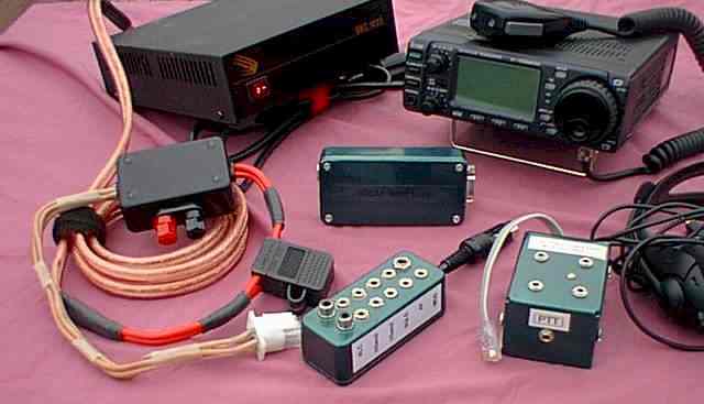
This picture shows the family of accessories in front of the Samlex SEC1223 power supply and the radio itself. Please click on this or other pictures on this page for a larger view.
The 706 is a darn small radio. The back panel is packed with either heat sink or connectors. Unlike many other ICOM radios, which connect to accessories via 8-pin and 7-pin DIN connectors, the 706MKIIG has a single 13-pin connector. This connector is conceptually similar to the pair of connectors on other ICOM radios. In fact, ICOM sells a special cable, the OPC-599, which breaks the 13-pin cable into an 8-pin and a 7-pin DIN connector. This allows the 706MKIIG to look like other ICOM radios.
I really wasn't interested in going this route. I would be adding a (probably expensive) cable, and still just be at connectors. I wanted the portable set up to be as small and compact as possible.
After looking at the signals on the 13-pin DIN plug, I noted that many were of immediate interest to me, especially the HSEND signal, which can be used to drive an external amplifier. Now I don't plan on running the 706MKIIG with an amplifier while portable, but as a backup radio, I did want to be able to use it at home (where I do use an external HF linear amplifier).
I should mention at this point that the 706MKIIG radio is shipped with an assembled 13-pin DIN male plug, that has an approximately 6 inch wire pigtail. ICOM correctly realized that trying to solder to that small and crowded connector would be beyond the skills and patience of most amateurs. They provided a short cable with the male connector already attached [It appears as if MFJ sells a 13-pin DIN plug with several feet of cable. This may be a good alternative to the ICOM cable].
I soon realized that I would never be able to once and for all figure out how I wanted to use the special cable that came with the radio, so my only alternative was to create a breakout box that would provide all of the signals on individual connectors. I would be using and making available all of the signals on the connector. All future configurations and connections would be possible.
Since my immediate concern was driving an amplifier, however, I decided to include that interface in the box.
The 706MKIIG does not have a signal which directly drives an external amplifier. What it does have is a pair of signals, HSEND (for HF and 6 meters) and VSEND (for 2 meters and 440 MHz). These signals, which are electrically similar, are bi-directional. The signals are pulled low (-0.5V to 0.8V) when transmitting. If you pull the line low, the radio will begin transmitting. While this bi-directional design allows lots of flexibility, it cannot directly drive an external amplifier.
Many different circuits have been designed for driving an amplifier. Simply search the Internet for ideas. I decided to build the circuit designed by Bob, K6XX. Bob's page also contains other important information about keying an amplifier from an ICOM 706. In particular, the leading edge of the 706 transmit waveform has a high power spike which will trip the protection circuit in some amplifiers. Fortunately, my amplifier, the Ameritron AL-1200, will work with the 706.
Bob's circuit uses two transistors and two resistors. My only change was to substitute a 2N2222 for the final 2N3904 (Q2). This should give me a little more power dissipation, although I would be surprised if it mattered.
I built my breakout box in a small metal enclosure, approximately 1.25" X 1.5" X 3.5". With 12 connectors, and a terminal strip for the amplifier driver, the box is quite crowded. I wired it up with the aid of a magnifying glass, using long nose pliers. It's not hard, just time consuming.
 |
 |
 |
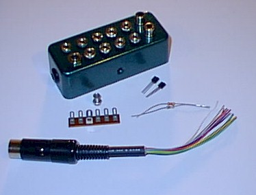
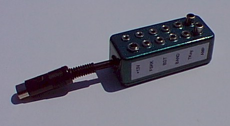
| Pigtail, Box, Parts | Completed Interface |
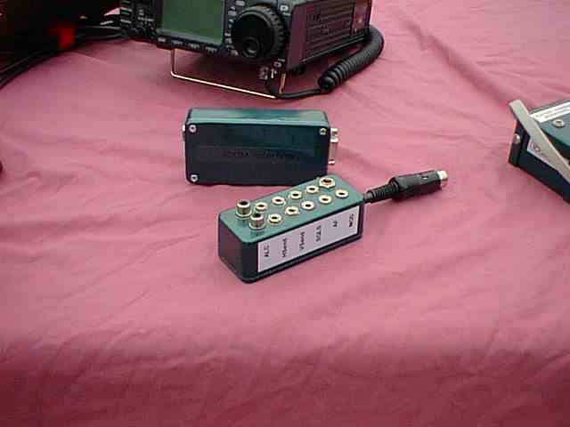
Interface near CI-V box and 706MKIIG |
The left picture shows the ICOM-supplied pigtail, the parts for the amplifier keying circuit (terminal strip, 4-40 bolt and locking nut, two transistors, and two resistors), and the box. You can see the 12 connectors mounted on the top of the box. The pigtail enters the box through a hole on the end, the left end in this picture. A grommet protects the cable as it enters the case, and also helps make a tight fit around the cable. Strain relief was an issue, and in the end, I used epoxy to lock the cable to the inside of the box. I did this after rotating the box on the pigtail cable so that the connectors would point straight up when the cable was in the back of the radio.
The choice of connectors are up to you. I tried to pick what I considered to be standard. The amplifier keying line, and the amplifier ALC line are brought out on RCA (phono) jacks. The +13.8V power is brought out on a 2.1mm power jack. The remaining 9 jacks are all female 1/8" (3.5 mm) jacks. The connectors are placed in two rows of 6 connectors each. The only signal which I did not bring out was the +8 V signal, provided to power electret condenser microphones. Since another wire provided the full 13.8 VDC at 1 Amp, I did not see a reason to bring out an 8 Volt, 10 mA signal.
The completed breakout box is shown in the middle picture. I made labels for each side of the box with my printer. I used mailing labels, which had an adhesive backing. After placing them on the box, I coated the side with several coats of clear spray paint to provide protection.
The right picture shows the interface in front of my homebrew CI-V interface and the radio itself.
If you are interested in rolling your own cable, Bux CommCo does sell the 13-pin DIN plug.
One final comment about the box. Because the ICOM-supplied pigtail is so short, the box must sit right behind the radio. It is probably best that the connectors point straight up so that it is easy to insert cables. When fixing the pigtail in the box, rotate the box on the cable so that the connectors point in the desired direction. Do this before securing the cable to the box. The cable is so short that the box cannot rotate on the end.
OK, I admit, a power cable is not that exciting. I needed one, however, and I tried to make it as functional as I could.
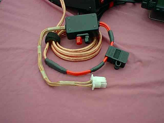 |
| IC-706MKIIG Power Cable |
While the radio is supplied with a power cable, at the least I wanted a cable with a tap for powering accessories. These accessories might be a CI-V interface, an automatic antenna tuner, or a small 12V portable light. One of the reasons I selected the Samlex SEC1223 switching power supply (available from AES) is that it provided 23 continuous amps. This would power the radio and have power left over for some accessories. Some switching supplies barely power the radio (when at full key-down transmit).
The power cable begins with 5 feet of monster-style speaker cable. This is the heavy gauge speaker cable that is used in high power audio systems. It is very flexible, and has a tough plastic coating. The speaker cable is spliced to a pair of automotive-style fuse holders. I used lots of heat shrinking tubing to keep the splice protected, as well as to bind the two fuse holders together.
All of the standard radio power cables I have even seen come with the old-fashioned round fuses. I believe that these are called 3AG fuses. In looking in my local parts stores, I could not find suitable fuse holders or fuses for this application. I asked a friend in the radio equipment business about this, and he believed that the 3AG fuses were used simply because they were traditional, and, they never seemed to blow out. Well, Murphy's Law would guarantee that sooner or later I would blow a fuse, possibly at a remote location. For 12 volt applications, it appears to make sense to switch to the newer automobile-style fuses. These are the plug-in fuses with two blades. These fuses are designed for 12 volt use, come in a wide variety of currents, and are available at many places. The fuse holders I purchased completely enclose the fuse, under a snap-on plastic cap.
Both the positive and negative wires are fused. I am currently using 25 amp fuses. Another (better choice) might be 20 amps. The power supply claims to trip at 23 amps, so in some sense, my fuses provide no real protection. If I switch to 20 amps, however, I will probably protect the power supply, but run the risk of blowing fuses in normal operation. This situation is the logical consequence of running a chain of equipment with little performance reserve. Of course the actual trip point of a particular fuse may vary. I will probably experiment with 20 amp fuses, and hope that the typical intermittent nature of SSB and CW will keep them from blowing. Since the power supply is protected, the fuses in this circuit are really there for the case of using a different power supply.
The outputs of the fuse holders go into a small plastic box that is used to mount a 3-way binding post set. This is the accessory tap. If you want some power, take it from this point.
The box provides one more important function. The power connector that actually goes into the radio is a 6-pin plug that appears to be standard among the amateur radio manufacturers. Two of the pins are unused, but the remaining four pins represent two +13.8VDC pins and two ground pins. So, at the least, any two wire power cable must be split into four wires. Some Kenwood cables run all 4 wires back to the start of the cable. That's one approach. Many ICOM cables hide the splice right at the connector, hidden under the plastic hood. In my case, I used about a foot of #14 flex-weave wire to go from the power connector back to the plastic box. The box is the junction point for the wires, as well as the location of the accessory tap. Heat shrink cable neatly holds the four wires together.
A word on the power connector itself. I purchased the connectors from a gentleman (Robert Langston, W2ENY) on the Internet. At the time of my order, three connectors cost $10 (USD). I sent him a personal check, and the connectors promptly came back. While the connectors do fit the radio, they are not identical to the ICOM connectors. The ICOM connector has a plastic hook that actually locks the connector onto the radio. These connectors do not have that hook. In my application, where the 706MKIIG is sitting on a table, the hook is not needed, since simple friction holds the connector onto the radio. But, if the radio was mounted in a more vertical orientation (such as in my mobile setup), the connector would probably fall out. Another possible source of power connectors is PowerWerx. I do not know if their connectors have the plastic hook just mentioned. Check GigaParts as another possible supplier. Finally, I have also become aware of Tower Electronics. They sell this connector with the locking tab and a plastic boot.
The 706 uses an 8-pin modular (telephone-style, RJ-45) connector for the microphone. The radio actually has two such connectors, one on the detachable front panel, and the other on the rear of the radio.
The 706 is similar to many other ICOM radios in that it prefers to be driven with an electret condenser microphone element. I have written about this on another page. For portable operation, I wanted to be able to use a headset that combines a microphone with headphones. Since I might be using the radio with a second operator, I wanted to be able to have two complete headsets connected to the radio at once. I expected to be using stereo headphones, so the two headphone jacks are stereo. The radio output is mono, so the left and right signals are simply joined together.
The other signal I brought out to a connector was the manual Push to Talk (PTT) signal. A foot switch can be plugged in to this jack for hands-free operation that does not rely upon VOX. This often makes sense in contest situations.
The choice of jacks was easy. All 5 (two microphone, two headphone, one PTT) are 1/8" (3.5 mm) stereo jacks. The ring connection is not used with the PTT jack.
I obtained the 8-pin modular plug from the end of a Radio Shack jumper cable (male to male). The flat cable is terminated on each end with an RJ-45 connector, so one cable provides two plugs. I cut the cable about 6 inches from the end. The cable enters the aluminum box through a grommet. I used epoxy to bind the cable to the inside of the case for strain relief. Please note that this cable is a flat cable that is usually used for telephone applications. This is in contrast to the round cable that is usually used for computer networking. The computer cable consists of 4 twisted pairs. I did not want to use that cable since the microphone signal and its ground did not line up as a single twisted pair. I also kept the cable length short in order to discourage noise pickup. On the flat cable, the microphone signal is located between microphone ground, and chassis ground. To me, this provides some measure of shielding.
After I cut off the end of the Radio Shack cable, I had my modular plug with 6 inches of wire. The next task was to map the wire colors back to the ICOM pin numbers. For my particular Radio Shack cable, and end, I found the following color versus pin number relationship.
| My Radio Shack Cable Colors versus Pin Number | ||
| Color | Pin # | Function |
| Blue | 1 | +8 VDC |
| Orange | 2 | Freq. Up/Down |
| Black | 3 | AF Output |
| Red | 4 | PTT |
| Green | 5 | Mic. Gnd |
| Yellow | 6 | Mic. |
| Brown | 7 | Gnd |
| Gray | 8 | Squelch |
Inside the aluminum box, I used a terminal strip to mount the two resistors and two capacitors which are part of the microphone input circuit. Here's the schematic of the interface.
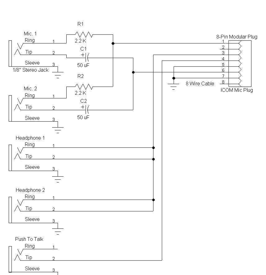 |
| Microphone Breakout Box Schematic (Click for full size view) |
Obviously you can build an interface for a single headset. In my case, the DC blocking capacitors I used were 50 uF. The value is not critical, so long as the microphone audio can pass through. I have used 10 uF in other cases. I simply happened to see some nice 50 uF capacitors on top of my junk box pile. NOTE: please consult my other ICOM microphone web page. In some cases, the external resistor and capacitor may not be needed.
With this box I can use any of the headsets designed for computer use (so long as they have electret condenser elements). These headsets are sold just about everywhere, and even the inexpensive ones provide good results.
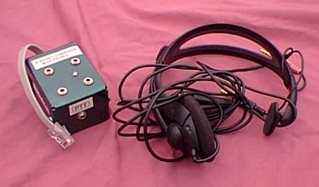 |
| IC-706MKIIG Microphone Breakout Box (and headset) |
I am currently using the Labtec Axis-501 single earpiece headset. At the time I bought it, the cost was approximately $15 (USD). The single earpiece design means that I can use it while operating mobile, even with VOX. I have tried this several times, and it does work well. The headset has an on-cable microphone on/off switch and a earphone level control, both of which are quite convenient.
When using the headphone jacks on the breakout box, the audio will not be muted from the radio. If you wish to mute the speaker, either move the headphone plug to the front panel of the radio, or, plug a dummy plug into the front panel jack.
Although ICOM radios include a computer interface, you cannot simply connect a radio to a computer with a serial cable (this is how Yaesu (in recent years) does it, however). The ICOM interface is built around the concept of a shared bus, where more than one radio or computer can be connected to a single physical communications channel. The physical channel is a so-called open collector bus, whereas a computer serial interface is based on the RS-232 standard.
This means that if you want to connect most ICOM radios to a computer, you must do so through an interface. The interface takes RS-232 transmit and receive levels, and combines them to a single open-collector point. This point can then be directly connected to an ICOM radio - or more than one ICOM radio, for that matter.
ICOM sells an interface box, but it is very expensive - well in excess of $100 (USD). Since the interface parts usually cost no more than $10 (USD), many, if not most, amateurs build their own. I believe that equivalent products are also available from third parties.
Many interface designs have emerged over the years. They seem to fall into one of two categories. The first category is based around the Maxim 232 integrated circuit. This chip is a complete RS-232 interface, including charge pump voltage converters that provide plus and minus 10 volts from a single plus 5 volt supply. The RS-232 standard specifies both positive and negative signal levels. Combined with a TTL open collector driver, such as the 7417, you have the primary components of the interface. One version of this design has been reproduced in the ARRL Handbook for years, and is the design that I have used. An example of this design can be found at: www.plicht.de/ekki/civ/civ-sch2.html.
The second interface design is built around several discrete transistors, and is usually powered from one of the unused RS-232 control lines coming from the computer. While this is attractive, some computers will not provide enough power to operate the interface, and the lack of a true negative supply voltage compromises the RS-232 standard. A typical schematic for this interface can be found at: www.plicht.de/ekki/civ/civ-sch1.html.
In fact, please consult the CI-V web pages of Ekki, DF4OR, for a whole range of interface designs and useful information.
My interface is really nothing more than the classic Maxim circuit - with one little wrinkle.
The computer interface is used for several different purposes. In most cases, the primary purposes of the computer interface are to enable computer logging and remote control of the radio from the computer. Both are implemented by moving data between the computer and the radio over the transmit and receive data lines. The computer interface has several other signals that can be useful in other applications. For me, I was interested in using an RS-232 control line to key the transmitter for modes such as PSK-31. In this case, the actual data goes across audio cables from the computer sound card to the radio. All the computer interface does is turn on the transmitter.
The problem is that serial interfaces are often in high demand on a computer. Several years ago, most computers came with two serial ports. In recent years, many computers contain a single serial interface port. This means that if you have more than one device that uses the serial port, you will be forced to swap cables. This is especially true on laptop computers, which usually only have a single serial port.
The wrinkle I added to my CI-V interface was to bring out the RTS serial port signal on a miniature connector. This means that I can use the interface for data transfer as well as transmit control, without having to swap cables. It still may be impossible to use more than one program at a time, since the serial port can only be used by one program at a time. But, I don't have to swap cables, and that's the majority of the inconvenience.
The interface is built in a small metal box. The computer connector is a DB-9 female connector. Power enters the box on a 2.1 mm standard power connector. The CI-V bus is provided on a 1/8" (3.5 mm) jack. The RTS signal comes out of the box on a 3/32" connector. I find that Jameco is a good parts source.
The details of my interface are presented on another page.
When driving in the car, the receiver audio can be easily covered up by traffic and road noise. Although I use an external speaker with the 706MKIIG, there are times when even more audio volume is desirable. For those times, I use a cassette tape adapter, which plugs directly into the front panel of the radio, and then plugs into my minivan cassette player. The unit I use is made by Sony, and is shown in the following picture. Click it for a larger view.
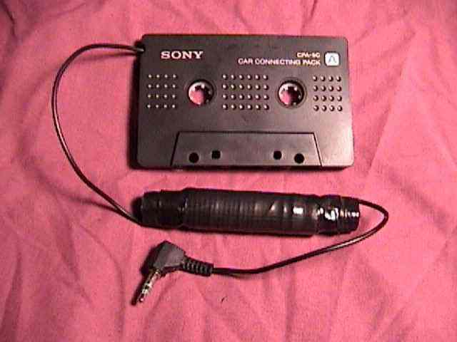 |
| Using a cassette adapter with an ICOM 706MKIIG |
My only modification to the unit was to wrap most of the cable around a ferrite rod to act as an RF choke. Since the cable was too long anyway, this let me reduce the length as well as improve noise immunity.
With this accessory, the receiver audio comes out of all 4 speakers in my minivan, and I have lots of volume, as well as tone controls. When the other station has a strong signal, it's really as if they are in the vehicle with me.
Back to my Experimentation Page