|
| Portable Station Pieces Parts |
Greg Ordy
On this page I will describe the components included in and organization of my portable station. The station is built around the ICOM 706MKIIG radio. This radio covers all bands and modes from 1.8 MHz through 440 MHz (excluding 220 MHz). My portable station is designed to operate on all of those bands, except for 440 MHz. The HF antenna is a center-fed dipole. The dipole is 88 feet long, and fed with 450 Ohm open-wire line. A 2 element Cubex quad is used on 6 meters, and it also has 4 elements on 2 meters. The quad is supported by a 28 foot tall aluminum pole. That same pole can be used to support the dipole at the 22 foot level.
The station breaks down into 4 major pieces. The first two are the radio, and a Dell laptop computer that I use for logging and other radio software. The third component is a box approximately 14" X 14" X 14". This box contains the antenna tuner, power supply, dipole, and all of the feed lines and cables necessary to set up the station. The final component is a box that contains the antenna mast and quad. This box is approximately 6" X 6" by 72". The two boxes weigh 30 and 20 pounds, respectively.
|
|
| Portable Station Pieces Parts |
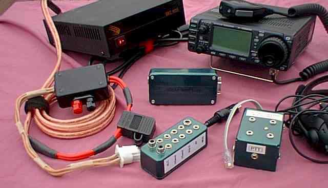
This picture shows the portable station spread out on a picnic table. The antenna mast and quad are not included in this picture.
My portable radio is an ICOM 706MKIIG. For logging and other radio-related software, I use a Dell laptop computer. Several accessories are used to connect the radio to the computer, as well as other parts of the portable station. These accessories are described on another page.
In addition to these accessories, it's a good idea to carry a GPS receiver, especially if your location matters. I had a situation during a VHF-oriented portable operation where I ended up in the target grid square by only a few thousand feet. The GPS is indispensable in those situations.
When AC power is available, I power the 706MKIIG through a Samlex SEC1223 switching power supply (available through AES). This supply weights only a few pounds, and is quite small, about the same size as the radio itself. The supply can provide 23 continuous amps. This will fully drive the radio, and provide a small margin for safety, and powering low-current accessories. Some switching supplies only provide 18 to 20 amps of current. While these supplies will usually work due to the low duty cycle nature of CW and SSB, I prefer to have a little more juice to begin with.
Part of the portable station design challenge is to minimize the number of tools needed to set up, operate, and take down the station. In this configuration, I need a 6-in-1 screwdriver, an open-end adjustable wrench, and a nutdriver. A hammer is also needed for driving in the antenna mast guy rope tent stakes. I also use a large number of Velcro fasteners to secure all of the cables and ropes. The fasteners I use are strips about 6 inches long. They have a slit on one end, and are similar to a belt. You put the strip around a bundle, slip the end through the slit, then wrap the excess on itself. These fasteners are easily reused, and quite convenient. I found mine at the local hardware store.
If you're looking for a simple multiband HF antenna, it's hard to beat a dipole fed with open-wire line. Conventional wisdom suggested that the length of the dipole be a normal 1/2 wavelength on the lowest frequency of interest. In my case, that would be 80 meters (although I would not mind 160 meters!). While an 80 meter dipole (approximately 132 feet long) can be used on the remaining HF bands (40, 30, 20, 17, 15, 12, and 10 meters), the antenna is so long that on the higher frequencies the pattern of the antenna breaks into a number of lobes with substantial gain surrounded by deep nulls. In addition, the direction of primary signal strength tends to rotate from broadside to endfire.
In practice, and especially in portable situations, the direction of the deep nulls may not be controllable, and, they may (unfortunately) fall in a desired direction.
Through antenna modeling and simulation, it has been discovered that it may make sense to use a somewhat shorter antenna than conventional wisdom suggested. On the lowest band, the antenna impedance will become less than 50 ohms, and some efficiency and bandwidth will be lost. This negative factor is more than compensated for by the improvement in the pattern on the higher bands.
L.B. Cebik, W4RNL, has a web page that includes a detailed analysis of this shortened all-band antenna. As in the case of all of his work and pages, it's very good reading and information.
Of course it hopefully goes without saying that an antenna tuner must be used to provide a match between the radio and the transmission line.
After reading the Cebik page, and several other sources, I decided to size my all-band dipole at 88 feet. Practically, a full-size 80 meter dipole, at 132 feet, can be difficult to install. By reducing the length to 88 feet, it becomes much easier to set up the antenna in many portable situations. I feed the antenna with 450 ohm open-wire line. I use my MFJ-949E antenna tuner to obtain a match on all HF bands. The 88 foot long dipole will also tune up on 160 meters.
 |
| HF Open-Wire fed Dipole and Tuner |
This picture shows the components used as part of the HF dipole. Most of the parts came from the Radioware and Radio Bookstore. I have made many orders from them over the years, and have always received good service.
The dipole wire is #14 plastic-coated Flex-Weave. This wire is a pure joy to use. It is very strong, and does not coil or kink. It has no memory. It is a stranded wire made with a number of very small strands. I also used this wire to make up two, 20 foot grounding jumpers. One end has an alligator clip, and the other end has a ring terminal. One or both of these jumpers can be used to connect the tuner to a ground point. These grounding jumps can be seen in the lower left corner of the picture.
The center insulator of the dipole is a WA1FFL Ladder Lock Center Insulator. This part is made from UV-resistant plastic.It provides strain relief for the open-wire line, and attachment points for the dipole legs and the support rope.
The rope used to support the dipole is 3/32" UV-resistant Dacron rope. This is another great product that I have used in many applications. It is very strong, and does not stretch or deteriorate. The center support is attached to approximately 70 feet of this rope. I include in the kit, two, 20 foot long ropes used for the ends of the dipole. I pack a spare length of rope for the ends or the center support, where ever it might be needed.
I attached 40 feet of open-wire line directly to the dipole at the center insulator. This length represents a reasonable length that will connect the dipole directly to the tuner when the tuner is located near the center of the dipole. I soldered banana plugs to the end of the open-wire line. The banana plugs can directly plug into the back of the MFJ tuner.
In some circumstances the tuner will be further away from the dipole. To handle these cases, I carry along three, 20 foot long open-wire jumpers. These jumpers have female banana plug jacks on one end, and male banana plugs on the other. I use the fewest number of jumpers necessary to connect the tuner to the dipole. I can select from feed line lengths of 40, 60, 80, or 100 feet. This system has worked out quite well. Tools are not required to connect the lengths together. It is usually a good idea to keep the open-wire feed line off of the ground. Wooden dowels or even sticks can be used as supports.
In most all cases, the dipole feed point impedance will not match the impedance of the feed line. This means that the line will be operating in a mismatched condition, and it will have standing waves on it. One of the reasons for selecting open-wire feed line is because it can tolerate higher SWRs with lower loss than coax. Because the line is mismatched, it will also be acting as an impedance transformer. Sometimes, increasing or decreasing the feed line length will make it possible to achieve a tuning match because the transformer action of the feedline will convert the dipole impedance into a value that the tuner can handle. For this reason, having the ability to change the feed line length is desirable. If you can't achieve a low enough SWR, try changing the feed line length. It may do the trick.
In order to simplify tuner adjustment, and to protect my radio, I usually use a portable antenna analyzer to aid in adjusting the tuner for lowest SWR. The Autek RF-1 tuner is ideal for portable operation because it is very small and lightweight.
The antenna wire, support rope, feed line, and center insulator are all available from the Radiowave Bookstore.
If all I cared about was HF operation, I would probably not even consider providing my own dipole center support. Most every portable site will include some point that can be used to support a dipole. The common tree has been used to support dipoles since the dawn of radio.
 |
| Cubex 6/2 Meter Quad with Antenna Mast |
I was interested in portable operation on 6 meters, however, and I wanted to get an antenna with some gain up into the air. My initial choice was the Cubex Hornet-X quad. This antenna is designed for portable operation, and can be collapsed into a bundle less that 4 feet long, and about 3 inches in diameter. The antenna has 2 quad elements on 6 meters, and 4 elements on 2 meters. Each antenna is fed with a separate coax cable.
My antenna tower/mast is made from aluminum tubing. A good source of tubing is Texas Towers. I had a number of sections left over from a vertical antenna project. They were pressed into service for this use.
I use five sections of tubing, each 6 feet long. The tubing telescopes together. Each joint overlaps by 6 inches, and a single hole is drilled through both tubes. The hole is located 3 inches from the ends of the tubes (halfway across the overlap). I use 2 inch stainless steel bolts with wingnuts to pin each joint. With 5 tubes there are 4 overlapping joints. Each one reduces the length of the mast by 6 inches. The overall length of the mast is 28 feet. 28 feet represents far more than a wavelength on 6 meters, and is high enough to clear many local obstructions. Even though this is a portable antenna, it's performance is good.
The maximum tubing diameter is 1 7/8 inches. Each telescoping tube is 1/8 inch smaller in diameter. The 5 diameters, therefore, are, 1 7/8", 1 3/4", 1 5/8", 1 1/2", and 1 3/8". The top tube is additionally drilled to accept a bolt that pins the quad boom to mast clamp plate to the mast. This is in addition to a pair of U-bolts that holds the quad to the mast. It takes only about 2 minutes to assemble the mast. The 5 sections of tubing are laid out on the ground. Two sections are telescoped together, and the bolt is added to pin them together. Do this 4 times and you have a 28 foot tall mast.
For shipping purposes, I telescope the sections together, but I alternate telescoping diameters, and end up with 2 tubes. In other words, I put the 1 3/8" tube into the 1 5/8" tube, and that into the 1 7/8" tube. The 1 1/2" tube is stored within the 1 3/4" tube. While the tubes do telescope, any minor dent or bend in a tube will make it impossible to telescope into the next sized tube. When the mast is in use, all that matters is the last 6 inches of a tube. But, for shipping, it is desirable to be able to get some space savings by telescoping the entire tube length. By skipping diameters, I hope that even if a tube dents or bends, it will not be enough to cause a problem. The price I have to pay for this is having two tubes in the collapsed position, as opposed to a single tube. From my experience with telescoping aluminum tubing, it would simply be impossible to get the entire 6 foot length of a tube to smoothly telescope in another tube, and to do this 5 times, and to be able extend it and retract it many times.
This mast must be guyed. It is not free-standing. I chose to use three guy ropes, and to locate the guy point at the first tubing transition down from the top. This is where the 1 3/8" tube telescopes into the 1 1/2" tube. Let's see - I have a directional antenna mounted on top of a guyed mast. I will not be using an antenna rotator. I will simply rotate the mast by hand - the so called Armstrong method. What that means is that the guy ropes cannot directly attach to the mast. If they are, the mast will not rotate. I needed a guy support that would allow rotation of the center mast.
In these cases, I use a special plate that I first saw used with the MFJ 40/80 meter top-loaded vertical antenna. It's a round plate of galvanized metal that has a large hole in the center for the mast, and a set of holes drilled at the edges. The holes are spaced to allow either 3-point or 4-point guying. The plate has a rolled edge that reduces wear and tear on the guy rope. The center hole is sized so that it stops and rests on the top of the lower tube at a telescoping junction. The plate sits on the top of the lower aluminum tube. The antenna mast is held at a given point in space, but is otherwise free to rotate inside the guy mounting plate.
The next picture shows this guy mounting plate along with the three guy ropes. Velcro strips are used to bind the guy ropes.
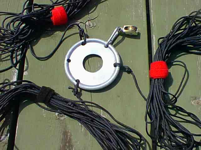 |
| Guy Mounting Ring with Guy Ropes and Dipole Pulley |
If you look closely at the picture, you will see a metal clip coming off of the plate, terminated in a small pulley. This pulley can be used to hoist up the HF dipole, should there be no other support available. Since the dipole is anchored to the plate, and not to the mast, it will be in a fixed position, even as the mast is rotated.
Tent stakes are used to fix the guy ropes to the ground.
It is a two person job to raise and lower the antenna mast. The quad is assembled, and attached to the mast. The two coax feed lines are dressed down the side of the mast. The bottom of the mast is determined. Two guy ropes are set in the ground at a spacing of 23 feet from the mast base. The guys are spaced 120 degrees apart, and are located evenly to each side of the quad.
One person takes the third guy rope, and the second person, starting at the quad, begins to walk up the mast. As the quad raises in the air, the person pulling on the third guy can take on more and more of the load. Finally, the mast comes vertical. It cannot over-rotate since the back two guys will stop from going further than vertical. When the mast is vertical, the third guy can be attached to the ground with a tent stake. The aluminum pole does flex, but it works just fine.
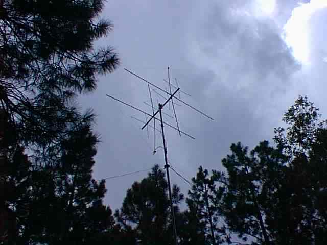 |
| Quad on top of Mast |
This picture shows the quad on top of the mast. You can see the guys slightly below the bottom of the quad spreaders. The antenna is rotated by simply turning the aluminum pole. Taking down the antenna and mast is also a two person job.
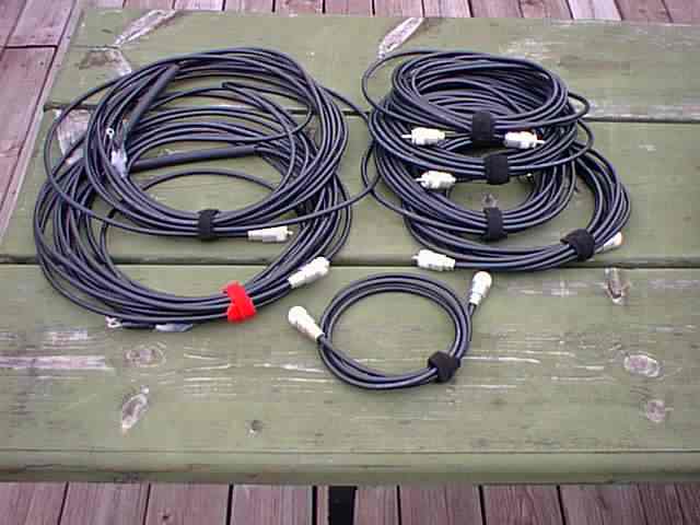 |
| Coax Cable Assortment |
I chose RG-8X coax cable for the 6 and 2 meter feed lines. Being a thinner cable, it does have loss which quickly accumulates, especially at VHF frequencies. Any thicker cable, however, is simply too bulky and heavy. So long as the cable runs are kept as short as possible, the loss is acceptable (especially at 6 meters).
I made two, 40 foot cables that feed the 6 meter and 2 meter driven elements. One end of the cables terminate in UHF PL-256 plugs. The other end has ring terminals. The ring terminals connect directly to the quad elements. For strain relief, I use 6 inch long pieces of rubber gasoline fuel line. The tube is slit down its length and placed around the coax. The two coax cables are held to the mast with a hose clamp. The clamp goes over the rubber tube, which protects the coax from direct pressure, and provides a friction grip along its length. The clamp is located right below the quad on the mast.
As in the case of the HF dipole, I carry several shorter jumpers which provide feed line extensions when necessary. I made up four, 20 foot cables with PL-256 plugs on each end. Standard barrel connectors are used to create a daisy chain of cable. I have one, 5 foot jumper which connects the radio to the antenna tuner.
The above picture shows all of the cable sections in the portable station package. Velcro straps keep all of the cables neat.
It always seems as if I am installing PL-259 plugs on coax cables. There are 12 plugs in that last picture. Up until a few years ago, I would rather walk on hot coals than install PL-259 connectors. Finally, as my antenna projects grew, I needed so many cables that I simply had to become proficient in installing connectors. Now, it seems easy, and I wonder what took me so long to get past that issue. I have described my process for installing PL-259 plugs on another web page.
Back to my Portable Operation Page