 |
| Gain Versus Take-Off Angle Comparison (Straw, QST, December, 2005) |
Greg Ordy
I set out to try to understand and build all of the 80 meter inverted vee designs that I could find. My sources of information were the books on my shelf, a basement full of old amateur radio magazines, and the Internet. While searching for information on broadband dipoles and vees, I came across a lot of information on the use of a reflector or ground screen under the dipole or vee, especially when the antenna is relatively close to the ground, and intended for NVIS (near vertical incidence skywave) communication.
In reading the material, there was a wide range of performance claims and theories of operation. This reminded me of what I was finding out about broadbanding claims - there were a lot, and they were sometimes difficult to reconcile with each other.
I decided to conduct my own experiments, and determine, in my very specific implementation, if I could detect any value in a ground screen under my inverted vee. Many sources claim that there is no meaningful improvement in performance, certainly not enough to justify the cost of the reflector under the antenna. Cost refers to the inconvenience of having wires running on the ground, or a few feet off of the ground, as well as the financial cost of the wire. Another group of sources suggest an improvement, but no more than a few dB, which is usually difficult to measure, and can be unimportant when local signals may already be 20 dB over S9. A minority of sources claim that the improvement can be dramatic. In most cases, these dramatic improvements appear to be associated with antennas that are very close to the ground, which usually suggests a lot of ground loss. Some claims suggest an improvement in receiver signal to noise ratio.
Factors such as antenna height and ground quality will influence the effectiveness of the reflector. The reflector itself can be constructed from a single wire, or, an elaborate two-dimensional screen. The size and height of the reflector can also be a factor. My point is that my results, whatever they are, may be difficult to generalize. As they say - your mileage may vary. The actual antenna element that I will be using in my tests will no doubt be uncommon. After all, my goal has been to find a wide bandwidth vee, and that will probably be an uncommon implementation. Will that difference skew my results? I hope and suggest that the answer is NO. Whether the antenna is a simple 22 gauge single wire, or a large cage or fan, I would like to believe that the effect of a reflector, counterpoise, or screen will be the same - if every other factor is held constant. If that assumption is incorrect, well, then, the value of my results will only go down.
Apart from the academic and curiosity value of trying to set up a test situation and taking some measurements, I really would like like to know if adding one or more wires, on the ground, under my inverted vee, would improve its performance in any meaningful way. My vee is at a location where adding the wires over winter would not be a problem. Since that's often times the most active season on 80 meters, I could simply put them out in the fall, and take them up in the spring. Wires off of the ground (5 feet is an often quoted height), however, would be a problem, and I will not consider those on this page. All of my reflector wires will be lying on the ground.
I have come to respect and pay attention to the writings of a number of amateurs who have earned that respect through decades of validated work and contribution. In the area of antennas, three names that come to mind are: John, ON4UN; Tom, W8JI; and L.B. W4RNL. Each has commented on the use of a reflector.
In the fourth edition of Low-Band DXing, by John, ON4UN, on page 8-7, he writes: The efficiency of low dipoles (1/4 wavelength high and less), which essentially radiate at the zenith angle (90 degrees), can be improved by placing wires under the antenna running in the same direction as the antenna.
In a message on the Tower Talk reflector at Contesting.com, dated July 21, 2005, Tom, W8JI, wrote:
Well, I'm in full agreement with the older Elmer. The only
thing that happens when a horizontal dipole antenna is installed significantly
lower than 1/4 wl is the efficiency drops, often like a rock!
Thirty years ago people knew if we wanted a dynamite NVIS signal we installed a
dipole at 1/8 to 1/4 wl high and laid a screen or grid of wires below the
antenna to reduce earth losses. Now we have people proclaiming in the best
interests of "Homeland Security" communications we need to use what really
amounts to a 10 dB or more attenuator on a 5 to 10 watt transmitter... rather
than building a good system.
This is probably why, when I listen to the GA ARES net, a significant number of
stations can't hear each other. Yet with a dipole 35 feet high over a large
ground screen I can hear and work all the dog-gnat signals coming from grossly
inefficient antennas that are (no surprise) quiet. This is where we are headed.
In a message on the Tower Talk reflector at Contesting.com, dated July 3, 2004, Tom, W8JI, wrote:
We always called the antenna an NVIR (near vertical incidence
radiator) antenna, and the mode was NVIS (near vertical incidence skywave).
It certainly isn't new. The first I heard of it was in the 60's when I first got
licensed.
Tuning the reflector 5% longer than resonance is largely a myth that I see
repeated quite often, as is the alleged S/N improvement with really low heights
(although at times that can work).
What you really need is several low counterpoise wires that can just lay on the
earth parallel with the antenna and generally longer than the antenna. I suppose
making a vertical yagi would work, but not with the reflector a few feet above
earth. At that height earth to reflector coupling would make tuning as a
reflector unlikely.
The idea is to minimize earth losses, which dominate low antennas. This is done
by providing an alternate path for currents. Contrary to rumor, improving
conductivity or adding a reflector does NOT suppress low angles. It simply makes
the entire system more efficient with very little pattern change. Without a
significant pattern change, there can be no signal to noise change.
L.B. Cebik, W4RNL, has several pages devoted to NVIS topics.
NVIS: From the Backyard to
Professional Installations models a number of different reflector
configurations. On anther page,
An Alternative Approach to a
Wide-Band NVIS Antenna System, on page 5, L.B. writes:
Virtually any horizontal antenna may serve at least as a narrow-bandwidth NVIS antenna if brought close enough to the ground. Therefore, the most fundamental NVIS antenna--widely used by amateur radio operators--is the simple dipole. Research suggests that the ideal height above ground for virtually any antenna in NVIS service is between 0.15 and 0.20
λ. Under these conditions, the antenna exhibits maximum gain at the zenith angle.Many NVIS antennas specify the placement of a second parasitic wire below the fed wire. The recommended spacing varies, but the practice is marginal at best. Research has shown that NVIS antennas tend to operate similarly to plane-reflector arrays, where the ground acts as the plane reflector. (Plane reflector arrays are widely used at VHF and UHF for such services as television and FM repeater communications.) If one is to place a reflector below the fed wire, it must have outer horizontal dimensions that extend about ½-
λ (at the operating frequency) beyond the limits of the fed-portion of the antenna.The lack of enthusiasm for the reflector (parasitic wire) is also expressed in the first link, where less than a dB is added to the signal strength by either a single wire, or, a seven wire plane.
Here are some of the references which I used or read in preparing this page.
Low-Band DXing, by John Devoldere, ON4UN (fourth edition in 2005, available from the ARRL). Although the previous quote is the only mention of this topic I am aware of in his book, the book has become the reference standard for low band (160, 80, and 40 meters) operation. It's chock full of useful information.
The web pages of Tom, W8JI, found at www.W8JI.com. Many topics are covered, far beyond antennas. Must reading for all amateurs. A specific NVIS page is: NVIS Antenna.
The Tower Talk and Topband reflectors at Contesting.com. (two specific links in the previous section)
The web pages of L.B., W4RNL, found at www.cebik.com. The pages are primarily about antennas, analyzed with computer modeling. Several pages are specific to NVIS topics. For example:
What's the Deal About "NVIS"?, by Dean Straw, N6BV, QST, December, 2005, page 38.
A search for NVIS or NVIS reflector will yield many hits with any of the popular search engines.
It is impossible to talk about reflectors under dipoles or vees without mentioning NVIS - near vertical incidence skywave. I was surprised to find a definition for NVIS in the popular Wikipedia. What I found even more surprising was that the few paragraph explanation also mentioned a ground wire, and included the claim that a gain of 3 to 6 dB was common (with the ground wire).
NVIS is a deliberate attempt to focus the antenna pattern straight up. When the ionosphere is reflecting signals (on 80 meters, that is usually the case at night), the reflected signals will tend to return at the same angle (the angle of incidence is equal to the angle of reflection). This means that communication with relatively nearby stations will be enhanced. Nearby is usually defined to be no more than several hundred miles. In amateur radio terms, this would include chatting between a group of nearby friends on 75 meters at night, or perhaps a regional net. Military and emergency response communication are also very interested in NVIS operation. Battlefronts, earthquakes, and floods tend to involve tactical distances of no more than several hundred miles.
One of the bits of conventional wisdom about antennas is that higher is always better. This is based upon the idea that a higher antenna has a lower take-off angle, which favors long distance (DX) communication. If the goal of all communication is to reach for the longest distance, than there is a lot of truth to higher is always better. But, of course, that's a false premise. NVIS is a term that includes an unstated bias toward shorter distance communication.
Taking things to extremes, which seems to be part of human nature, suggests that DX is the opposite of NVIS, and if higher is better for DX, then lower must be better for NVIS. Some folks have taken that thinking process to heart, and are suggesting erecting NVIS dipoles only a few feet off of the ground. While they may indeed work, all evidence I can find suggests that low dipoles are very lossy, and give up 6 to 12 dB of signal strength as compared to the same antenna a little higher up (see the W8JI and W4RNL references).
In the most simple model of propagation, a radio wave shoots into the sky at some angle, reaches a reflective layer of the ionosphere, and then reflects back down to the at the same angle, hopefully finding a receiving antenna when it reaches the ground. That is indeed a very simplistic model. It is conceptually similar to shining a flashlight against a mirror.
Even though the term take-off angle is used heavily when folks talk about antennas, the last thing that the term means is that energy leaves the antenna at some single angle, some single direction. The take-off angle usually refers to the angle (it can be measured in both the elevation and azimuth planes) where the radiated power is relatively highest. When you move away from that angle, the signal strength usually slowly starts to drop. Yes, antennas can have nulls in their pattern, but even a large null, like let's say 30 dB, means that the power in the null is reduced by a factor of 1000 as compared to the main lobe. It's not zero - it's relatively reduced by a factor of 1000.
An upcoming section presents some two-wire vertical Yagi pattern plots. If you examine the first plot on the left, which is a simple dipole, 40 feet high, the 3 dB beamdiwth is 118 degrees. This means that you can move nearly 60 degrees away from vertical before the power in that direction drops in half. This 3 dB reduction is a common reference point for measuring the width of a lobe. So, while the take-off angle is 90 degrees (straight up), we can drop to just about 30 degrees, and still find half of the power radiated at the 90 degree angle. The point is, energy is being sprayed across a large section of the sky.
The next interesting part of the journey takes place when that distributed smear of energy reaches the ionosphere. Again, using a simple model, one of three things can happen. The energy can be absorbed, it can be reflected back to earth, or, it can simply pass through the ionosphere and head out into space. Two of those cases - absorption and passing out into space, are pretty useless for terrestrial radio applications, since all of our antennas are back here on earth. Radio wave propagation is the study of the interaction radio waves with the ionosphere. There are many web pages that cover the topic, and many printed references. The ARRL Antenna Book has an entire chapter on the subject.
The ionosphere rarely treats radio waves like an optical mirror, which is relatively perfect in reflecting light waves. The height at which some degree of reflection takes place will vary from around 35 miles to well over 100 miles, being a function of the level of ionization, and the frequency, and other more minor factors.
But, even with all of these variables, the general idea that the radio wave bounces off the ionosphere and returns to earth is a useful model. Just don't think of it as a sharp laser beam hitting a perfect mirror, it's very far from that. And, it is almost always the case that putting more energy nearly vertical will cause nearby stations to receive a stronger signal. That's what NVIS is all about. [one counter example is when an antenna, such as a vertical, has both a strong vertical and horizontal signal component. It is possible that nearby stations will receive one component directly, and the other after shooting up and bouncing back down. These two components will usually be out of phase, and in the extreme will cancel. This happened when AM broadcasters tried to use 5/8 (0.625) wavelength verticals, due to their gain. But, they also have a substantial high vertical take-off angle component. The result was relatively close regions of signal nulls, which were a problem. As a result, the length in many cases was reduced to slightly more than 1/2 wavelength (190 electrical degrees). This reduced the low take-off angle gain by about 1 dB, but greatly reduced the straight up lobe, which got rid of the fade zones.]
The previously listed QST reference, authored by Dean Straw, N6BV, presents the following table of data, which relates take-off angle to distance.
|
Average Elevation Angles for Target Destinations |
|
| Distance (Miles) | Average Elevation Angle (Degrees) |
| 43 | 80 |
| 75 | 78 |
| 160 | 63 |
| 185 | 60 |
| 350 | 44 |
| 450 | 42 |
| 530 | 30 |
| 950 | 18 |
| 1500 | 8 |
|
Table 1 from QST Reference |
|
The somewhat strange set of distances comes from the fact that the table was generated for a set of cities surrounding San Francisco. I believe that this data is valid for other locations. It is important to note the term average elevation angle. It is not the angle, but rather the average angle. It's also true that if you attempt to construct an isosceles triangle from the two ground points, and the reflection point in the ionosphere, you will find that the height of that reflection point is not constant as a function of distance. I assume this data was generated by using modeling tools and data which is viewed as being reliable. I believe the data is also designed to represent the 80 and 40 meter bands.
wfwef
In explaining any gain increase after adding a reflector, it seems to me that there are two possible theories that could be at play - either individually, or in some combination.
In the Yagi theory, the added wire acts like a reflector on a two-element Yagi. What you have is a two-element parasitic Yagi which is pointing straight up, and the reflector is on the ground, or very close to it. When you see the reflector size called out as the antenna size plus 5%, this is a good sign that the Yagi theory is in play, since that is the rule of thumb for the reflector size on any other Yagi. Another sign of the Yagi theory is the suggested spacing of 0.15 wavelength between the antenna and the reflector.
In the case of any directional antenna, gain in one direction must come at the expense of gain in some other direction, so long as the efficiency is held constant. This is the classic balloon analogy for directional antennas. If you take a balloon and squeeze it in your hands, it will bulge out in some direction, which represents gain. But, at the same time, some other dimension of the balloon will shrink, which represents a gain reduction. This might also be called the no free lunch rule for directional antennas - we are redistributing the power as a function of direction, not, adding more power. In our case, the added gain going straight up would be at the expense of the response in other directions.
This change in the antenna response pattern could be part of an improvement in the signal to noise ratio. The main source of atmospheric noise, especially in the summer months, is lighting discharges, potentially up to thousands of miles from the antenna. It is claimed that this noise arrives at relatively low angles (see the Dean Straw December, 2005 QST reference). If the Yagi theory is true, then we should have a reduced response to low angle signals, since we have focused the response straight up.
This change in pattern suggests that the reflector might add gain for some take-off angles (and, therefore, distances), but reduce gain for others. This implies that it might be desirable for the reflector to be optional, used when it helps, and not when it hurts. That idea is suggested in one of the references, where a switch is used to break up the reflector and effectively make it invisible.
If we are following the Yagi theory, then we should be able to determine an upper bound for the additional gain. That number would be 3 dB. In general, you can add up to 3dB every time you double the number of elements in a directional array. This holds true whether you are going from 1 to 2 elements, 3 to 6 elements, or, even 10 to 20 elements.
In a normal parasitic two-element Yagi, the reflector will have approximately the same current magnitude as in the driven element. That is something that we can measure. The response may also be frequency dependent. After all, we are only 5% longer at one frequency. One way to investigate this is to measure the current in the reflector as a function of frequency (or change the length of the reflector, but that's more work). Another interesting measurement to consider is the feed point impedance when the reflector is added, and observe if it follows the trend of a typical two-element Yagi. In general, the impedance drops.
I must admit that I am not very comfortable with the idea of taking a two-element Yagi and bringing the reflector down to the ground. That just doesn't seem like a very good idea. Since the reflector is so close to the ground, it's correct physical length is probably not the nominal 5% longer than the active element. I decided to model a typical NVIS vertical Yagi, and capture its performance as a function of height off of the ground. The results are presented on another page.
The efficiency theory is based upon the premise that the reflector is designed to act as a shield between the antenna and the earth and reduce ground losses. The efficiency theory suggests that a larger ground screen or set of parallel wires is more effective than a single reflector wire. The idea is to create a large planar reflector, as opposed to a single reflector wire. Another way to say it is that the goal of the reflector is to improve the local ground conditions in the largest area possible.
The antenna response pattern does not change if all we are changing is the efficiency. This means that the signal to noise ratio does not change. Both signal and noise will increase or decrease by the same amount.
Can we put some bounds on the additional signal strength (gain) that we can expect according to the efficiency theory? Obviously the maximum efficiency is 100%. If the antenna without the reflector is 50% efficient, then we have a maximum improvement of 2X, which is approximately 3dB. If the antenna with the reflector is 25% efficient, then we have the potential for 6 dB of added gain.
If you read the W8JI and W4RNL references, it is clear that very low dipoles can have losses in excess of 10 dB as compared to the same antenna at a height such as 0.25 wavelength. This suggests that there is a lot of gain that can be picked up, if the efficiency can be raised.
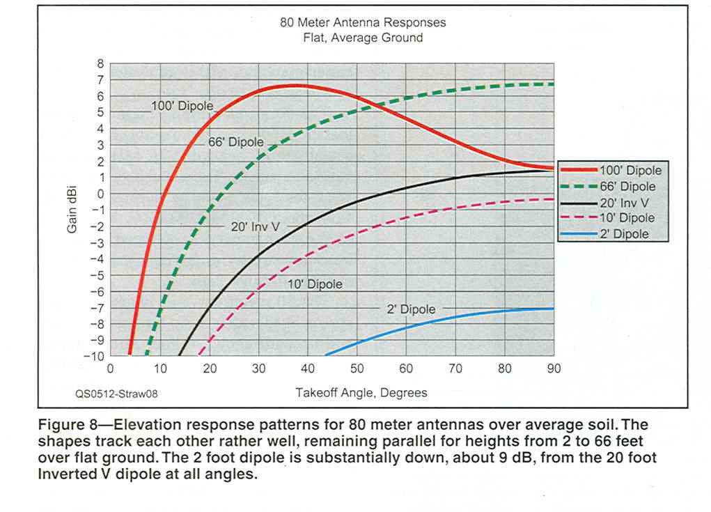
The information from ON4UN, W8JI, and W4RNL seems to favor the efficiency theory over the Yagi theory. My own sense is that the reflector is most useful when it is improving the efficiency of a very low dipole. Adding the reflector adds gain, but so would simply raising the very low antenna! Once the single antenna is at 100% efficiency, then there is no more to be gained. All that would be left is to exploit the Yagi mode of operation, which may be most compromised by being close to the ground. If the driven element is very high, such as 0.5 wavelength, then the Yagi might be very helpful in improving the gain in the vertical direction. As a dipole starts to approach 0.5 wavelength off of the ground, a null starts to open up in the vertical direction, which is very undesirable for NVIS operation. The following graph, from the Dean, N6BV, December, 2005, QST reference cited above, compares the gain versus take-off angle for a number of different antennas. I believe that these are simulation results. Please click on the picture for a larger view.
|
|
| Gain Versus Take-Off Angle Comparison (Straw, QST, December, 2005) |
As the graph shows, for nearly vertical take-off angles, a dipole 20 feet off of the ground offers about the same performance as a dipole 100 feet off of the ground. The 10 foot high dipole is only about 2 dB down from that level. Similar results can be found on this page.
In my case, my inverted vee has an apex of approximately 52 feet, which is very close to 0.2 wavelength (3.8 MHz). Many sources cite that as an ideal NVIS height. I also believe that my ground quality is above average, being rural midwest farming soil. All of this suggests to me that I'm at the higher end of the efficiency range. If I were at 70% efficient, and were able to move to 100% efficient, then that would be a 1 dB increase, which might be very difficult to measure, and, will not bring much practical benefit. This has been my thinking going into the experiment and measurements - that I will not be able to measure an increase in signal strength. This is because I'm high enough in the air to have a high efficiency, and that the ground quality under the antenna is good, and is not significantly lowering efficiency which a reflector could then overcome.
Let me state that idea with a metaphor which is a little crazy, but it's all that I can think of at the moment. Reflector wires are like a ladder that we can stand on to become taller (more gain). But, we are only allowed to use the ladder if we place it in a hole (less than 100% efficiency). In fact, the height of the ladder is always about the height of the hole. If we are on level ground (near 100% efficiency), then then ladder is very short and pretty useless. The question becomes, why not just stand on level ground, as opposed to climbing in hole, and then standing on a ladder, to end up at the same point? The previous graph, from Dean Straw, shows that the 2 foot high dipole always has lower gain than the 10 foot high dipole. I suspect that even reflector wires would not help the 2 foot high dipole, although they might help the 10 foot high dipole.
Of course in some circumstances, it may be impossible or too time consuming to get the antenna at the necessary height. That's fine, and for those situations, a reflector may be a great way to boost efficiency.
CURRENT, IMEPEDANCE, MEASURE SIGNAL STRENGTHS
wefwefwef ANTENNEA SMETER LITE, RELAYS
wefwefwef CHANGES TO FEED IMPEDANCE.
I must confess, I am fascinated by the historic development of the broadband 80 meter dipole, and it's close relative, the inverted vee. The bandwidth of a 1/2 wavelength dipole is normally only an issue on 80 meters, where the desired coverage can span 500 KHz, at 3.5 MHz. I suspect that 160 meters could be a problem too, but it seems as if few operators operate across the whole band. Either they are happy down at the DX end, or, up higher at the ragchewing end.
RESONANCE, NOT NEEDED, MATCH, LOSS, COAX, OPEN WIRE BROADBAND FEED, NOT ANTENNA. CEBIK, QST, FAN,
wefwef
Since I was unable to detect any performance change due to reflector wires under my normal inverted vee, and the goal of this page was to search for a performance change, I decided to continue the experiment with a different dipole. The material I read and the measurements I made suggested that my inverted vee was operating with a high enough efficiency that the influence of any reflector wires was undetectable. My inverted has a DIPOLE EQUIVALENT HEIGHT of 43 feet, which is near the optimum height for NVIS antennas (on 80 meters). I also believe that the ground conductivity under my antenna is above average, and I was making my measurements in the fall season, when the ground is usually constantly wet, which will improve its conductivity even more. If the reflector wires were to increase the efficiency by 10, 20, or even 30%, the change in signal strength would be no more than 1 dB, and that's a difference that I can't reliably detect.
If reflector wires can increase the efficiency of a dipole or vee, and if the vee starts off at a high efficiency, then the only choice to see a positive effect of the reflector wires is to lower the efficiency of the antenna before the reflector is added. The way to do this is by physically lowering the antenna, increasing the ground loss.
I constructed a new dipole on another part of the yard. This dipole is supported by 10 foot tall center and end poles. The height of the dipole can be set to any value from lying on the ground to 10 feet in the air. What sort of performance should we expect from a 10 foot (high) dipole as opposed to a 43 foot dipole. We can use the data presented in the QST reference as a starting point. Please click on the graph for a larger view.
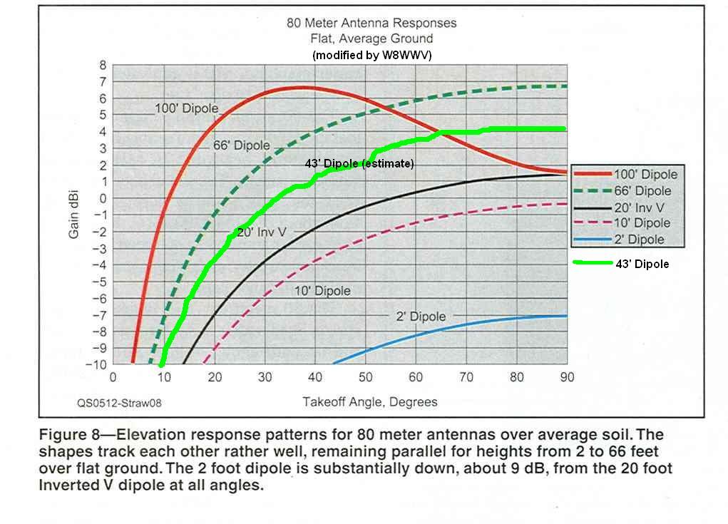 |
| 10 Foot Dipole versus 43 Foot Dipole (Straw, QST, December, 2005) |
The original data included a 66 foot dipole and a 20 foot dipole. 43 feet is halfway between those two values, and I have draw a new green line which is halfway between the 66 and 20 foot data. The interpolated data suggests that the 10 foot dipole should be 4 to 5 dB below the 43 foot dipole. The difference is fairly constant as a function of take-off angle, although it appears to be a little larger at lower angles.
So, the data going into the experiment suggests that the lower dipole should have about 4 to 5 dB lower gain than the normal vee hanging off of my tower. Assuming we see some drop in gain, the next question becomes - can reflector wires help recover any of that loss?
A few points before getting into the measured data. First, the dipole was constructed from the same #14 stranded wire that I have used over and over again for various projects. I initially cut the antenna to be 60' 6" per side. This is a few inches longer than the length which had a 3810 KHz resonance point when hung off of my tower as an inverted vee. As in the case of my other dipoles and vees, a Radio Works B1-2K balun was used at the feedpoint.
I first supported the dipole from the center pole alone, with both ends falling to the ground. Measured through approximately 50 feet of RG-8X (mini-8) cable, with an MFJ-269 antenna analyzer, no SWR dip could be detected. I then elevated one end of the antenna, and the antenna started to show a slight dip a little below the 80 meter band. After getting the entire dipole at the 10 foot level, the SWR dip was all the way down to 1.0, at 3808 KHz. This tracked the inverted vee resonance point quite closely for approximately the same antenna length.
I measured the following SWR data as a function of frequency:
| 10 Foot Dipole SWR Response | |
| SWR | Frequency |
| 3.0 | 3650 KHz |
| 2.0 | 3710 KHz |
| 1.0 | 3808 KHz |
| 2.0 | 3896 KHz |
| 3.0 | 3958 KHz |
The 2:1 SWR bandwidth was measured at 186 KHz. The SWR bandwidth of the tower-mounted inverted vee was measured at 210 KHz, a slightly higher value. So, although the low dipole may be involved with more ground loss, that loss is not increasing the antenna bandwidth, which is often times a property of loss. In fact, the 3:1 SWR bandwidth of the low dipole was approximately 300 KHz, whereas the higher inverted vee showed a 400 KHz bandwidth between the 3.0 points.
Here is a very crude map showing the location of the dipole, the inverted vee, and my 80/40 meter vertical array.
If there are any interactions with the surrounding antennas, any measurements made might be tainted by the coupling between them. The distances and orientations are such that I believe that the interaction is very small, if any at all. In any case, given the size and dimensions of my yard, this is about as far apart as I can get the antennas.
Note that the dipole and inverted vee are orthogonal to each other. This would cause a major problem in comparing signal strengths between the two antennas, except for that fact that both antennas are so close to the ground that they exhibit essentially omni directional responses. To the extent that the responses deviate from omni directional, it is at low elevation angles, and I should be measuring mainly high take-off angle signals. In order to make sure that any antenna orientation gain is not getting confused with height off of the ground gain, I need to compare signals that are known to be lying along the east-west or north-south axes. If the vee had the classic bar bell response pattern, then it would be stronger in the east-west directions. The low dipole, being orthogonal to the vee, would be stronger in the north-south directions. Again, I hope that this won't be a factor, and ideally, the vee and dipole would have the same orientation. In the case of my yard, that was not possible.
FIELD DAY, PORTABLE, EMERGENCY, CARRY GROUND WIRE.
FIRST GET TALL< THEN ADD REFLECTOR, BUT IF YOU MUST BE LOW, EXPERIMENT WITH A REFLECTOR, COULD BE A LOT THERE TO GAIN.
IS IT EASIER TO RAISE THE ANTENNA TO INCREASE EFFICIENCY, OR, ADD A GROUND SCREEN? FOR EMERGENCY PORTABLE TEMPORARY INSTALLs, the ground wire may be easier. ESPECIALLY TRUE OVER POOR QUALITY SOIL.
WHEN YOU LOWER A DIPOLE DOWN TO LIKE 20 feet on 80, or 10 feet on 40, YOU WILL FIND THE NOISE DROPPING, SINCE THE LOSS IS ACCUMULATING. NEED TO MEASURE S/N CAREFULLY, AND MAKE SURE THAT YOU ARE BEING HONEST. JUST TURN ON YOUR RECEIVER ATTENUATOR AS A TEST, THAT CAN OFTEN TIMES SEEM TO IMPROVE THE S/N, ALTHOUGH WE KNOW THAT IT CAN't.
Back to my 80 Meter Inverted Vee Page
Back to my Experimentation Page