 |
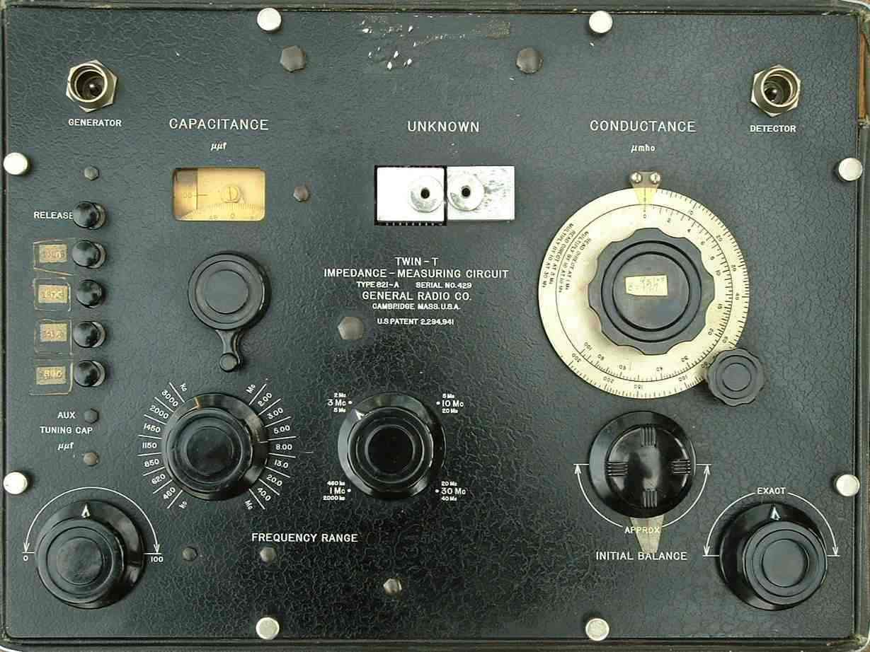 |
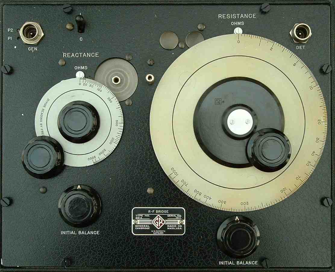
| General Instrument 916-A RF Bridge | General Instrument 821A Admittance Bridge |
Greg Ordy
On another page I measured a range of impedance references on three contemporary antenna analyzers. This page makes similar tests against two traditional impedance bridges. The bridges are the General Radio 916-A RF Bridge (GR 916-A), and the General Radio 821-A Twin-T Admittance Bridge (GR 821-A). Here are pictures of these two classic units. Please click on a picture for a (much) larger view.
|
|
|
| General Instrument 916-A RF Bridge | General Instrument 821A Admittance Bridge |
I would like to thank George, W5YR, for parting with the 916-A, and Val, W8KIC, for loaning me the 821-A.
This 916-A dates back to the year 1947, and the 821-A dates back to 1955. For many years, these were state of the art laboratory-grade devices. To this day, they still provide high accuracy results, although they are awkward to use, and lack the convenient user interface of the contemporary microprocessor-based unit. On top of being useful and accurate, each unit is a mechanical work of art, coming from a time when accuracy was based on precise components and high quality construction.
I have no idea if either if these units is correctly calibrated. Their performance reflects their state after largely sitting around for decades. Perhaps their performance can be improved, I simply don't know.
Early in 2005, Pete, N8TR, was kind enough to lend me his Boonton 250-A RX Meter. This device is described near the end of this page.
The concepts behind these bridges are very simple. The bridges are used in conjunction with a signal generator and detector. If you look closely at the upper left and right connectors on each box, you will see that they are labeled Generator (or Gen) and Detector (or Det).
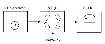 |
| Typical Bridge Measurement Block Diagram |
The generator is usually an RF signal generator, although in more recent bridge systems a wide-band noise source might be used (then the term noise bridge might be used). So long as your detector is narrow-band, the generator can be wide-band. The detector is usually a receiver. The only other connectors on the front panels of these units are the connectors for the unknown impedance. Neither bridge requires a power supply. So long as you keep them in good shape, they should survive for a very long time.
Like most bridges, the design places reference components in one leg of the circuit, and unknown components in the opposite leg. RF is applied at the generator input, at the desired frequency, and the detector is tuned to the same frequency. The reference components are adjusted for a balance, which implies a null. The null causes the detector (receiver) to indicate a minimum signal level. On my ICOM 706MIIG receiver, which is my usual detector, the null depth is at least 100 dB, and very sharp. When you have achieved balance, you can read the results from scales around the reference controls (knobs).
Here are two very simple impedance bridge schematics.
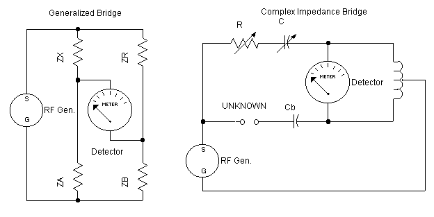 |
| Simple Impedance Bridge Schematics |
The left schematic shows the classic bridge taken right out of any textbook. Assuming ZA is equal to ZB, then when ZX (unknown) equals ZR (reference) the detector will read zero. Within reason, the values of ZA and ZB don't matter, but they must be equal if we are to assert that ZX equals ZR when the detector reads zero. In order to measure resistance (and impedance in the general case), we need one variable reference resistor (ZR), and two matched resistors (ZA and ZB).
One of the many possible variations is shown in the right schematic. ZA and ZB are implemented as inductive reactance. The implementation must make sure that each leg is identical to the other. Variable reference resistance R balances the resistance in the unknown impedance. Variable reference capacitor C balances the reactance present in the unknown impedance and the series bias capacitor Cb. By cleverly choosing the values of C and Cb, the range of C will include both inductive as well as capacitive reactance.
The circuits found in the 916-A and 821-A are extremely different than these simple conceptual designs. There are a lot of details not covered here.
The RF generator signal is divided to run down each leg of the bridge. When the reference resistance and reactance are equal to the unknown resistance and reactance, the output of the bridge will be zero - a null. When the bridge is not balanced, generator signal can reach the detector. In practice, the null is very sharp. The S meter on my receiver starts off pinned at S9 + 60 dB. When I'm very close to the null, the signal level may drop by 10 dB. You know that you are not too far away. The hunt is on. At this point, you have to move the knobs by the smallest possible amounts. A nudge is almost too much. Finally, the signal will drop to S0. It's a little like adjusting an antenna tuner for a 1.0 SWR, but much sharper.
Practical use of these bridges is complicated by several factors. First, finding the null is a skill that takes time and practice to develop. At least two controls representing resistance and reactance must be slowly rotated until the null appears. Unless you are very patient, you will think that something must be broken, since you just can't find the null. When I was first learning to use these devices, it would take me at least 5 minutes to find a null. Even when I'm in top form, it takes at least a minute to find a null. A single measurement requires establishing at least two nulls, one to initially balance the bridge with the particular test leads, at the particular frequency, and the second to actually make a measurement. In some cases, it takes additional null detections to arrive at the final answer. On the 916-A, for example, it takes 4 null detections to measure capacitive reactance with the highest degree of accuracy. By the way, the initial balance is made with trimmer controls, and the final balance is made with the calibrated reference controls.
Once you have the readings from the dials, you may have to make additional calculations to arrive at the desired units. The impedance bridge reactance dial measures Ohms, and can only be directly read at 1 MHz. If you are at some other frequency, you must divide the dial reactance by the frequency in MHz in order to arrive at the true reactance. The 821-A reactance dial reads directly in units of capacitance, which must be converted if you are looking for Ohms, or inductance.
Beyond these initial calculations, it may be necessary to make additional compensation calculations that address a whole range of errors due to issues such as frequency or lead length. Each operating manual contains several charts and graphs which can be used to determine correction factors for the initial measurements.
In today's world it's common to use a program such as an Excel spreadsheet in order to make these final calculations. Thank goodness, since operations such as taking a square root can be required. I have this vision of an engineer or technician, one or two generations before me, with their white shirt, narrow tie, and flat-top short haircut with a generator, bridge, detector, and slide rule, out at the base of some AM broadcasting antenna, making measurements. More than 50 years ago it was possible to make accurate measurements - even with the narrow tie.
Both units become more difficult to use as the frequency rises. I'm not sure that I would enjoy making measurements much above 10 MHz. At some point the impact of your body starts to effect the null. The practical impact is to slow the whole process down, and it's already too long. The various corrections and compensations tend to become more important as the frequency rises, so their impact cannot be ignored.
An applet for the 821-A can be found on the Internet. The applet is provided by Kevin Schmidt, K9CF.
The admittance bridge is somewhat the inverse of the impedance bridge, since it directly measures conductance and capacitance as opposed to resistance and reactance. These differences suggest the best application for each device. The 916-A impedance bridge is easiest to use when measuring typical antenna and transmission line impedance values, such as when resistance and reactance are under 100 Ohms. The 821-A admittance bridge is easiest to use when measuring components such as capacitors and inductors. The manuals detail the procedures used to make nearly all measurements with each device, but when you stray from the direct reading dial information, you get easily bogged down in computations, corrections, and probably errors.
These devices can measure relatively subtle effects such as the loss within a capacitor. It's typical to consider a capacitor as being lossless, but they do have loss, often expressed as the dissipation factor. Even a small fraction of a percent of loss can be measured. On the 916-A it's very easy to measure the loss of an inductor. Once you know the resistance and reactance, you can compute the Q of the inductor, which can be very important in many situations.
As mentioned before, there are two typical impedance measurement ranges common to amateur radio applications. The first is what I will call low impedance values, typically found in antenna and transmission line measurements. An example is the measurements made at the input to a section of coaxial cable terminated with a mismatched load. In this case, I will be using the same cable and termination used to make measurements with several antenna analyzers on another page. Resistance values are under 100 Ohms, and reactance, both positive and negative, is in a similar small range near zero.
The other typical measurement range is what is found with reactive components, capacitors and inductors. In those cases, the reactance can be hundreds to thousands of Ohms. The resistance, on the other hand, is usually near zero, since these components ideally have no resistance. In many cases, the resistance can be ignored, so long as it is low. If you want to compute metrics such as component Q, you need a very accurate resistance measurements made at a very low value.
Each of these ranges will be considered separately. In the end, and by nothing more than dumb luck, I happened to have at my disposal two devices with opposite characteristics. The admittance bridge was best for making component measurements, and the impedance bridge was best for making transmission line and antenna measurements. The admittance bridge is several years newer than the impedance bridge, and it appears to be a more accurate and flexible device. On the other hand, it is probably more difficult to use.
The 821-A will not directly make low impedance measurements. The reactance control measures capacitance, and is marked in units of picofarads (pf). The control is a very precise mechanical capacitor which spans 1000 pf, and can be read to a resolution at least 0.1 pf. In best use, the dial is set to some initial reading where the bridge is balanced (the first null) without the device under test (DUT) connected. The DUT is connected, and the second null is found. The difference, in pf, between the initial and final settings directly indicates the capacitance of the device. If the device is an inductor, capacitance must be converted to inductance by first converting to reactance. Additional compensations may shift the value a little, but for the most part, this is how you measure reactance. The relative relationship between the magnitude of the initial and final settings indicates whether the reactance is capacitive or inductive.
Ideally, the initial and final readings should both fall on the dial without any other adjustment to the machine. If there is an adjustment, then it must be factored into the difference between the two readings. That adds a step which can take time, and contribute to error. Part of using the machine effectively is understanding how to set it up so that the initial and final readings can be both measured with the same set up. It's clear that if the span in capacitance is more than 1000 pf, you have no hope of finding a single set up, since the entire range of the reactance control is 1000 pf.
My low impedance test values come from the transmission line and 25.2 Ohm load described on another page. The reactance cycles between approximately +36 and -36 Ohms. Picking an example frequency of 3.5 MHz, 36 Ohms of capacitive reactance equates to 1263 pf - already greater than the direct reading span of the machine. 10 Ohms of reactance equates to 3548 pf, an even larger span.
Clearly, the low reactance values would require a span larger than what's available on the bridge. The solution suggested in the manual is to add a capacitor in series with the bridge. Two readings are now made, one with just the auxiliary capacitor, and the second is the series combination of the auxiliary capacitor and the device under test. Since this is a series combination of reactive components, the impedance difference is the impedance of the DUT.
While this procedure is sound in theory, there are practical issues. First, we now have to find three nulls as opposed to two in order to make a single measurement. Second, we have to create a mechanical lash up that combines the parts with the shortest interconnecting wires so that we are measuring the DUT, not the wires. Finally, the value of the auxiliary capacitor is important. We want a value which has two properties at the same time. First, it should have the largest span on the reactance dial to improve accuracy, but it must also have a value which causes the conductance control to reach a null within its range.
When I was experimenting making measurements at 2 MHz, I found that a 47 pf auxiliary capacitor did not have enough span to make it possible to resolve the difference in impedance, and a 500 pf capacitor would not produce a null on the conductance control. 100 pf worked fine, but it was no longer usable above 5 MHz. So, you can spend a lot of time trying to get a working set up.
As an example, at 2 MHz, with a 100 pf auxiliary capacitor, the impedance of the capacitor alone was 0.09 - j 820.29 Ohms. The series combination of the auxiliary capacitor and the transmission line was 24.69 - j 807.03 Ohms. The difference is 24.9 + j 13.26 Ohms. How does this compare to the expected values? Here is a table with the computed values and the measured values. This table only includes 3 frequencies, since I had about as much fun as I could stand with the procedure.
| Comparison of 821-A Bridge versus Lowband Software Computed Values | ||||
|
821-A Bridge |
Lowband Software | |||
| Freq. (MHz) | R (Ohms) | X (Ohms) | R (Ohms) | X (Ohms) |
| 2 | 24.60 | 13.26 | 27.61 | 12.42 |
| 3 | 29.25 | 20.25 | 31.08 | 18.71 |
| 4 | 35.22 | 27.03 | 35.56 | 24.95 |
While the values track, their accuracy is not very good. I suspect that better results could be obtained with more practice in selecting and using an auxiliary series capacitor. Since two intermediate measurements are combined to make one final measurement, it is much easier for error to creep into the picture. In this case, we are trying to measure the difference between two reactance values that are around 800 Ohms at 2 MHz, and 400 Ohms at 4 MHz. The error difference between the measured and computed values is approximately 2 Ohms. It would seem very easy to accumulate that amount of error when the result is the difference between two measurements.
Where the 821-A shines is in measuring components - inductors and capacitors.
The problem with checking component accuracy is finding known reference components. I looked through my supply of silver mica capacitors, and found several 1 percent, 2 percent, and 5 percent tolerance pieces. I measured those with the 821-A. The following table compares the measured values against the markings on the capacitors. I made measurements at 3.8 MHz. A more complete approach would have been to measure the capacitors at several frequencies between limits such as 2 MHz and 30 MHz. My own interest was in the amateur bands between 1.8 MHz and 7.3 MHz, so 3.8 MHz seemed to be a nice middle of the road frequency.
| Reference Capacitors Measured at 3.8 MHz on 821-A Bridge | |||
| Component | Measured (pf) | Impedance | Q |
| #1, 430 pf, 1% silver mica | 433.87 | 0.07 - j 96.53 | 1459.5 |
| #2, 430 pf, 1% silver mica | 430.06 | 0.07 - j 97.39 | 1451.3 |
| #3, 430 pf, 1% silver mica | 429.83 | 0.07 - j 97.07 | 1454.3 |
| #4, 625 pf, 2% silver mica | 619.60 | 0.14 - j 69.65 | 811.6 |
| #5, 33 pf, 5% silver mica | 31.61 | 0.86 - j 1329.9 | 1324.9 |
| #6, 560 pf, 5% silver mica | 579.90 | 0.06 - j 72.23 | 1124.8 |
| #7, 820 pf, 5% silver mica | 751.48 | 0.05 - j 55.73 | 972.4 |
All readings were well within the tolerance printed on the capacitor, with the exception of part #7, which measured a little on the low side.
The 821-A has enough resolution to allow the measurement of component Q. The challenge is to measure the very small resistance through the capacitor or inductor. I used it on several web pages to measure the Q of RF components and transmission lines. While these measurements do not prove accuracy, they show that the device has enough resolution to measure large reactance and small resistance at the same time. In some cases, there are comparisons with computed values that suggest that the 821-A is quite accurate.
The 916-A does a good job with antenna/transmission line measurements. It appears to have been targeted for that application. I was once told that there was a time when every AM radio station had a 916-A which was used to make measurements for their records and the FCC.
If there is an issue with the 916-A it is that it requires 4 nulls to make a capacitive reactance measurement, as opposed to 2 nulls for inductive reactance. If you don't know the sign of the reactance, you are forced to make a initial measurement which won't lead to any useful data other than the sign of the reactance. Given that, you can set the L/C switch at the top of the cabinet.
As before, measurements were made of the transmission line with a 25.2 Ohm load which I used to evaluate several antenna analyzers.
| Computed Versus 916-A Measured Impedance Values as a Function of Frequency | ||||||
| Lowband Software | 916-A Measured | 916-A Corrected | ||||
| Freq. (MHz) | R (Ohms) | X (Ohms) | R (Ohms) | X (Ohms) | R (Ohms) | X (Ohms) |
| 2 | 27.61 | 12.42 | 28.00 | 12.00 | 28.00 | 12.09 |
| 3 | 30.69 | 18.71 | 31.20 | 18.83 | 31.20 | 18.96 |
| 4 | 35.56 | 24.95 | 36.20 | 24.50 | 36.20 | 24.69 |
| 5 | 42.87 | 30.72 | 43.50 | 30.00 | 43.50 | 30.27 |
| 6 | 53.44 | 34.93 | 52.30 | 33.30 | 52.30 | 33.68 |
| 7 | 67.69 | 35.17 | 69.00 | 32.57 | 69.00 | 33.15 |
| 8 | 83.79 | 27.65 | 84.20 | 23.75 | 84.20 | 24.51 |
| 9 | 95.31 | 10.89 | 93.80 | 5.56 | 93.80 | 8.08 |
| 10 | 94.43 | -12.14 | 89.00 | -15.60 | 90.78 | -13.32 |
| 11 | 81.95 | -28.45 | 76.80 | -30.00 | 78.34 | -28.50 |
| 12 | 66.02 | -34.77 | 61.60 | -35.42 | 62.83 | -34.65 |
| 13 | 52.40 | -33.93 | 47.80 | -33.85 | 48.77 | -33.50 |
| 14 | 42.42 | -29.55 | 39.80 | -29.29 | 40.60 | -29.06 |
| 15 | 35.55 | -23.81 | 33.40 | -23.67 | 34.07 | -23.50 |
| 16 | 30.64 | -17.01 | 29.20 | -17.88 | 29.78 | -17.72 |
| 17 | 28.19 | -11.51 | 26.80 | -12.00 | 27.34 | -11.82 |
| 18 | 26.69 | -5.42 | 25.50 | -6.06 | 26.06 | -5.87 |
| 19 | 26.31 | 0.60 | 24.60 | 0.00 | 25.34 | 0.32 |
| 20 | 26.99 | 6.62 | 25.50 | 5.90 | 26.52 | 6.27 |
| 21 | 28.83 | 12.66 | 28.20 | 11.71 | 29.33 | 12.21 |
| 22 | 32.02 | 18.72 | 33.00 | 17.73 | 34.32 | 18.48 |
| 23 | 37.07 | 24.64 | 36.80 | 22.83 | 38.27 | 23.82 |
| 24 | 44.50 | 29.91 | 43.90 | 27.71 | 45.66 | 29.14 |
| 25 | 55.03 | 33.35 | 54.00 | 29.80 | 56.16 | 31.82 |
| 26 | 68.73 | 32.59 | 66.80 | 28.27 | 69.47 | 31.08 |
| 27 | 83.40 | 24.30 | 79.20 | 19.63 | 82.36 | 23.21 |
| 28 | 92.87 | 7.21 | 86.00 | 1.07 | 89.44 | 5.07 |
| 29 | 90.87 | -13.01 | 79.60 | -18.79 | 84.37 | -14.56 |
The measured values indicate the readings taken from the dials. While they are approximately accurate, you can improve their accuracy by applying several correction factors. The corrected value columns contain the corrected values. The resistance correction was estimated to be 1.02 for values between 10 and 20 MHz, and 1.04 for values between 20 and 30 MHz. One could interpret the graphs in the manual with more accuracy, these are estimates on my part. The reactance is compensated through the use of equation 6a in the manual. That probably is useless information for everybody but me. I want to remember what I did when I look at this again in a year, and I've otherwise forgotten everything about the measurements!
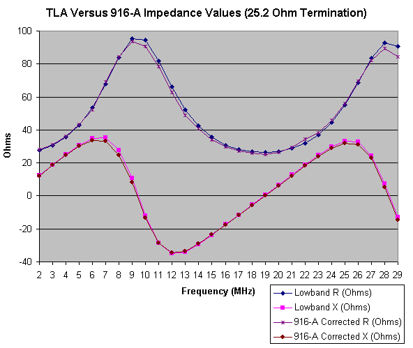
As I did on the page where I compared computed data against antenna analyzer measurements, here is a graph of the computed data plotted against the 916-A corrected data.
 |
| Comparison Between TLA Computed Data and 916-A Corrected Data |
The 916-A does a good job of following the expected values, although there are some differences at the resistance and reactance maximum values. The 916-A data follows a very smooth curve. I don't know what happened with the resistance at 23 MHz, where the data has a greater deviation from the expected, and a deviation from the curve. This might be a measurement error on my part.
I measured the same reference capacitors and frequency used in the component impedance measurements in the previous 821-A section. Because the 916-A is an impedance bridge, I converted picofarads at 3.8 MHz into Ohms of capacitive reactance. This comparison will be based upon Ohms.
| Reference Capacitors Measured at 3.8 MHz on 916-A Bridge | ||||
| Component | Reactance (X) Ohms | Measured X Ohms | Impedance | Q |
| #1, 430 pf, 1% silver mica | -97.5 | -94.7 | 0 - j 94.70 | X |
| #2, 430 pf, 1% silver mica | -97.5 | -95.79 | 0 - j 95.79 | X |
| #3, 430 pf, 1% silver mica | -97.5 | -95.80 | 0 - j 95.80 | X |
| #4, 625 pf, 2% silver mica | -67.0 | -66.58 | 1.15 - j 66.58 | 57.9 |
| #5, 33 pf, 5% silver mica | -1280.0 | -1166.80 | 0 - j 1166.80 | X |
| #6, 560 pf, 5% silver mica | -74.8 | -71.1 | 0 - j 71.1 | X |
| #7, 820 pf, 5% silver mica | -51.1 | -51.58 | 0 - j 51.58 | X |
Because we can measure resistance as well as reactance, it is possible to compute the component Q, which is reactance divided by resistance. Unfortunately, while the reactance values are reasonable, the resistance is clearly not very reliable. The 821-A looks capable of measuring Q, but not the 916-A.
With the exception of the 33 pf capacitor, the other readings were made with the 4 null technique. When the reactance of the item under test is more than around 1000 Ohms, the 4 null technique no longer applies. Only 2 nulls are needed. Fortunately, the scale on the dial is not as compressed for large capacitive reactance changes, so the accuracy is not greatly compromised.
Early in 2005, Pete, N8TR, was kind enough to let me borrow his Boonton 250-A RX Meter. This is a 1974 vintage admittance bridge with integrated oscillator and detector. Although it's one large 40 pound box, it requires no additional equipment to make a measurement. It contains 7 vacuum tubes, used in the oscillator and detector. It consumes 60 watts of power. Being a newer device, it is probably more easily available than the 916-A or 821-A General Radio bridges. In checking prices on the Internet (2005), I saw one (used) for $1200.00 (USD). I suspect that they cost much less at hamfests or flea markets, when you can find them.
The frequency range is 0.5 to 250 MHz. This far exceeds the other bridges. The resistance range stops at 100,000 Ohms. The capacitor range is 0 to 20 pf, although this can be extended by using additional external components. The inductance range is a function of frequency, starting at 100 mH at 0.5 MHz, and dropping to 0.4 mH at 250 MHz.
Here is a picture of the meter. Please click on the picture for a larger view.
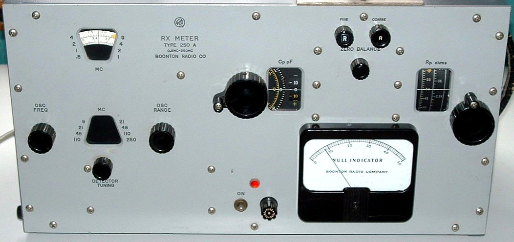 |
| Boonton 250-A RX Meter |
Like the General Radio bridges, the mechanical quality of the device is very high, especially by today's standards. The Cp and Rp knobs drive multiple turn controls that have very precise indicators. The frequency (oscillator) control can only be described as wild. There is a range knob, with fixed settings, and a fine tuning knob to select the frequency within the range. As you change the range knob, an internal shutter exposes various portions of a large dial within one of two holes in the front panel. This is a very clever way to implement a bandswitching mechanism which provides a lot of linear distance, but takes up very little room, and does not require a huge number of knob turns to arrive at a target frequency. The frequency readout is a little coarse, but digital frequency counters are a dime a dozen, and can be used with the meter to indicate the precise frequency.
The detector output is shown on a large meter. I found this meter easier to use than the S Meter in my ICOM 706MKIIG radio, which is what I used with the General Radio bridges.
The direct reading dials measure Cp and Rp, the parallel form of capacitance and resistance. These can be converted to series form, and other useful quantities, through the use of formulas. Pete provided me with a floppy disk that contained an Excel spreadsheet which accepted the parallel form right from the dials, and computed a number of electrical parameters.
I find these (General Radio) bridges to be more than accurate enough for the vast majority of amateur applications. They are inexpensive when you can find them on the used market. They would easily add character to any 1950's science fiction movie.
What they lack is ease of use. You need a signal generator and a receiver just to get started. Each measurement requires at least two nulls. Up to four nulls can be needed in some cases, such as measuring capacitive reactance on the 916-A. You can spend a minute or more taking a reading, even if you are proficient at finding nulls. It's relatively easy to make measurement errors, due to required conversions and compensations. These devices are also easiest to use when you are holding the frequency constant across a series of measurements. This is often not the case in many typical situations, usually when you are trying to sweep a range or band of frequencies. When you change frequency, several adjustments and conversions can change. The risk of error is increased, and a little more time is required to make the next measurement. This is the opposite of the popular antenna analyzer, where you can just spin the frequency knob, and watch the readings change in real time. Reading are made easier and faster when you have an good approximation of the result, so that you can head for the null, as opposed to stumble around looking for it. If you have put the correction factors into a program, they are easy to use, so long as you remember to set up all of the values. With a program, manual computation of correction factors is tedious at best.
Each device is easiest to use when you follow their intended function, and stay within their direct reading ranges. The 821-A admittance bridge is excellent for measure the value of inductors and capacitors at radio frequencies. This includes the loss resistance, which results in the computation of the component Q. It is awkward to use the 821-A to measure low impedance values, such as common with antennas and transmission lines. The 916-A, on the other hand, does a good job of measuring relatively lower impedance values typically found on transmission lines and antennas. It has a harder time measuring typical component values, especially the resistance.
Both units become more difficult to use as the frequency increases. Just touching the knobs tends to shift the nulls. When they are specified to operate up to around 50 MHz, I found them a little too touchy above 20 MHz. The issue is not so much accuracy, but time, as it seems to take longer to take a reading.
In the case of the recent microprocessor-based antenna analyzer, there is little room for operator error, except that which comes from using long interconnecting wires. The traditional bridge somewhat compensates for lead length, assuming that you null the bridge with the test leads in place. The opportunity for operator error, is much greater, however, due to all of the dials and settings and compensations. This is all time consuming and can make a short evening seem very long. I suspect that I am not a very good operator, simply because I lack the experience. Still, in the end, the accuracy is remarkably good for devices which are over 50 years old.
The Boonton bridge was much easier to use than the bridges which are 25 years older. If you are willing to lug the Boonton out to the antenna, and drag an extension cord with you, it could be used in the field. The General Radio bridges are right at the edge of being practical to use in a portable setting, since they are about as large and heavy as the Boonton, but require an RF generator and a detector.
Back to my Experimentation Page